
ISSN: 3005-8198 (online) | 3005-818X (print)
Volume 3, Issue 1 (January - March 2025) Pages 25-41
In recent decades, polymeric fibers have garnered heightened interest as a substitute for steel reinforcement due to their corrosion resistance, high tensile strength, and lightweight properties. Nevertheless, their linear elastic stress–strain response and absence of a plastic stage impede their application in compression members, particularly in RC columns and earthquake-resistant sections, as stipulated by design codes. In order to address these limitations, this study explores a hybrid reinforcement combining steel and polymer bars to balance strength, ductility, and durability. A finite element model was developed using ANSYS and validated against published experimental data, enabling the comparison of steel-, polymer-, and hybrid-reinforced concrete columns under combined bending with equal elastic moduli for steel and polymer bars. The findings indicated that polymer-reinforced columns exhibited a 16% higher load capacity compared to steel-reinforced columns, though steel columns demonstrated superior ductility. Hybrid columns exhibited approximately 9% greater load capacity than steel columns while demonstrating enhanced plasticity, suggesting that they provide an economical and durable alternative, particularly in environments prone to corrosion and moisture exposure. This research underscores the potential of hybrid reinforcement in achieving both structural efficiency and sustainability in concrete column design.
Keywords: Concrete, Steel, FRP, Polymers, Elastic Modulus, Plasticity, Hybrid, Eccentric.
The behavior of steel bars following yielding due to the plastic phase is a subject of particular interest, as it complicates the structural recovery and return of buildings to service after an earthquake. Achieving consistent yielding stiffness in reinforced concrete (RC) columns is also challenging. These limitations, in conjunction with long-term corrosion concerns, have prompted the exploration of alternative materials for steel reinforcement. Fiber-reinforced polymer (FRP) bars have garnered mounting interest as a reinforcement for structural elements due to their corrosion resistance, high tensile strength, and low weight. However, their linear-elastic stress–strain response and absence of plasticity limit their application in compression members, such as RC columns. This renders the concept of hybrid reinforcement—the combination of steel and FRP—a promising solution to balance ductility, strength, and durability.
A number of studies have documented the utilization of carbon fibers in concrete mixes for the fabrication of hybrid-reinforced columns under cyclic loads (Yuan et al., 2019), the implementation of steel bars longitudinally wrapped with basalt fiber-reinforced plastic (FRP) fibers as longitudinal reinforcement for concrete columns (Sun et al., 2017), and the testing of columns reinforced solely with steel or carbon FRP (CFRP) bars (Elchalakani & Ma, 2017). However, there is a paucity of research addressing the hybrid reinforcement of RC columns under combined bending with controlled elastic modulus between steel and FRP bars.
Current design codes continue to exercise caution. The ACI 440.11-22 (American Concrete Institute Committee 440, 2023) discourages the utilization of FRP bars in compression regions due to their restricted compressive contribution. In a similar vein, CSA S806-12 (R2021) (Canadian Standards Association, 2021) acknowledges the limited role of FRP in compression, emphasizing the necessity for specific guidelines and further experimental validation for its application. Concurrently, ACI SPEC-440.12-22 (American Concrete Institute Committee 440, 2022) underscores the durability advantages of FRP for infrastructure exposed to aggressive environments, while ACI SPEC-440.6-08(17) (American Concrete Institute Committee 440, 2008) highlights their cost-effectiveness in replacing steel. Indeed, polymer bars have already been applied in North America, Europe, Japan, China, and Australia in projects where corrosion poses a major risk (Qureshi, 2023). However, the low elastic modulus and brittle failure behavior of these materials underscore the necessity for hybrid reinforcement systems that leverage the strengths of both materials.
Recent research has expanded the understanding of FRP behavior and hybrid reinforcement systems. AlNajmi & Abed (2020) investigated the compressive behavior of GFRP and BFRP bars and confirmed that while FRP can withstand limited compressive stresses, its contribution in RC columns remains marginal. As demonstrated in the seminal work of Yuan et al. (2018), hybrid steel–FRP columns exhibit enhanced strength and ductility under cyclic loading when combined with engineered cementitious composites (ECC) to control cracking. In a similar vein, Ahmad et al. (2025) examined columns with steel and GFRP reinforcement under eccentric loading conditions and observed substantial enhancements in load-bearing capacity and ductility when compared to columns constructed of a single material. Pang et al. (2024) further developed predictive models for hybrid steel–GFRP columns under eccentric compressive loads, showing that reinforcement ratio and concrete strength significantly influence column performance.
Other contributions have focused on material innovations and structural behavior under lateral or cyclic actions. Elkafrawy et al. (2024) presented a state-of-the-art review, which summarized more than 250 studies on GFRP RC columns. The review emphasized knowledge gaps in hybrid reinforcement, slenderness effects, and combined bending scenarios. Zhou et al. (2023) enhanced the compressive capacity of FRP (fiberglass-reinforced plastic) by developing a hoop-wound GFRP (glass-filled resin) bar, reporting increased modulus and reduced brittleness. Tavakol & Haji Kazemi (2025) compared the cyclic lateral performance of steel-, FRP-, and hybrid-reinforced columns, concluding that hybrids provide an optimal compromise between ductility and durability. Hussain et al. (2025) advanced this concept by proposing hybrid cross-sections with the placement of fiber-reinforced polymer (FRP) externally for durability and steel internally for ductility, thereby demonstrating enhanced energy dissipation and corrosion resistance. Rodsin & Parichatprecha (2025) introduced a novel hybridized basalt fiber-reinforced polymer (FRP) system with promising load capacity under preliminary testing, while Tu et al. (2019) reported that longitudinal glass fiber-reinforced polymer (GFRP) bars contribute only 3–7% to ultimate axial load in compression, reinforcing the necessity of combining FRP with steel to achieve adequate column capacity.
Despite these advancements, there remains a paucity of validated computational models that capture the behavior of hybrid steel–FRP RC columns under combined bending, particularly when both materials are assumed to possess equal elastic modulus for direct comparison. A review of the extant literature reveals that previous studies have focused on axial compression, eccentric loading, or cyclic lateral forces. However, these studies have not addressed compound bending scenarios in a comprehensive manner. To address this knowledge gap, this study proposes a finite element model implemented using ANSYS Workbench 2022 R1, which has been validated against published experimental data sets. This model is employed to analyze the behavior of hybrid RC columns. The model is employed to draw parallels between hybrid reinforcement with pure steel and pure FRP reinforcement with respect to load capacity, ductility, and plasticity, thereby establishing a framework for the rational design of hybrid RC columns that combine durability with structural efficiency.
The research of (Elchalakani & Ma, 2017) at the University of Australia in the West in 2009 is related to the present research, which is an experimental study.
This study comprised an experimental investigation of 17 concrete specimens and 13 reinforced concrete (RC) column specimens, which were subjected to various loading conditions until failure. The objective of this study was to ascertain the impact of eccentric loading on RC columns and to examine the effects of plasticity, stirrups spacing, and axial capacity (Elchalakani & Ma, 2017).
The sample’s height is 1200 mm, and its cross-sections measure 260 by 160 mm. This volume guarantees that the samples are sufficiently large to be regarded as full-size specimens, thereby ensuring their suitability for testing using the Amsler apparatus at the Construction Experimentation Laboratory at the University of Australia in the West (Figure 1).
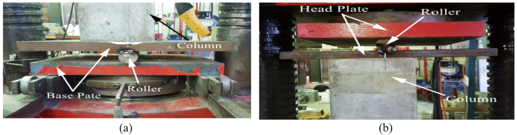
Figure 1. Eccentric Loading Setup by 2000 kN Capacity Apparatus; (a) Base Plate, (b) Head Plate (Elchalakani & Ma, 2017).
Nine samples were polymer-reinforced bars, while the remaining eight samples were steel-reinforced bars.
In this experimental program, the steel-reinforced RC columns were detailed with six N12 longitudinal bars and R6 steel stirrups. Four specimens were reinforced at a spacing of 150 mm, and the remaining four were reinforced at a closer spacing of 75 mm. Concurrently, the polymer-reinforced RC columns were constructed using six #4 longitudinal GFRP bars combined with #2 GFRP stirrups, once more with four samples reinforced at 150 mm and four at 75 mm. All specimens were cast using concrete with a maximum aggregate size of 10 mm, as per the specifications outlined in AS 3600. This concrete was designated as Grade 32 MPa. A schematic representation of the steel- and GFRP-reinforced column configurations is provided in Figure 2. The GFRP bars utilized in the study were manufactured in Canada, and the final testing of the V-ROD GFRP reinforcement was carried out by Hadi and Associates, ensuring material compliance and consistency with the experimental requirements (Elchalakani & Ma, 2017).
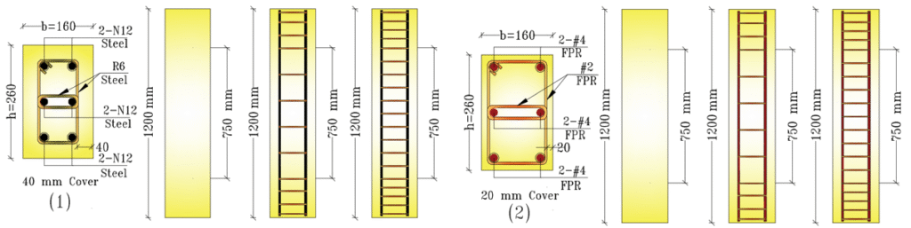
Figure 2. Reinforcement of Samples (1): Steel-Reinforced RC Columns with N12 for Longitudinal Reinforcement and R6 for Transverse Reinforcement, (2): GFRP-Reinforced RC Columns with #4 for Longitudinal Reinforcement and #2 for Transverse Reinforcement (Elchalakani & Ma, 2017)
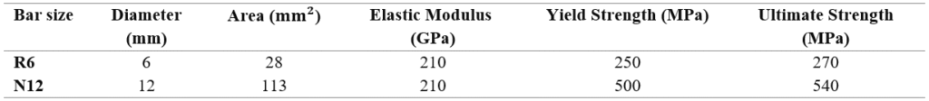
The test area, measuring 750 mm in diameter, is situated at the center of the column. Additional stirrups are positioned above and below the 225 mm test area. The concrete cover for steel-reinforced column samples was placed at a distance of 40 mm from the stirrups, as specified in the Australian Standard. However, the concrete cover was reduced to 20 mm for polymer-reinforced concrete column specimens due to their high corrosion resistance (Elchalakani & Ma, 2017). Tables 1 and 2 show the physical properties of the glass-polymer and steel bars, respectively while Figure 3 shows failure of samples from experimental study. Table 3 shows the mechanical properties of the samples, which involve 12 RC column samples.
Table 1. Physical Properties of Glass-FRP Bars
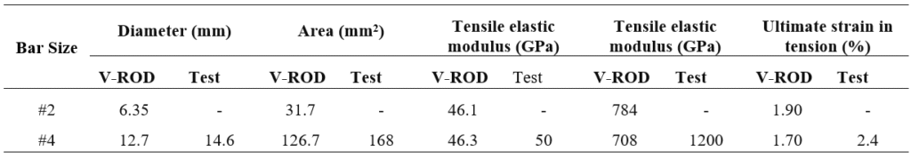
Table 2. Physical Properties of Glass-FRP Bars
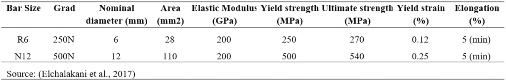
Table 3. Mechanical Properties of the Samples
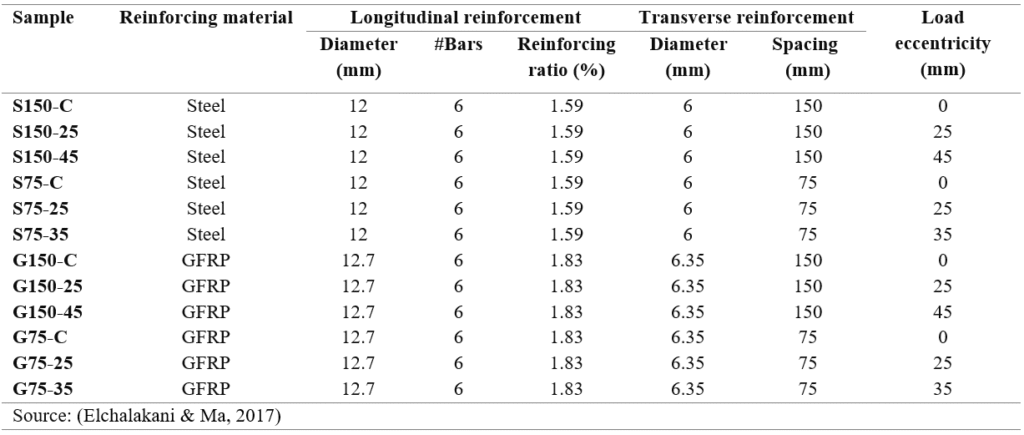
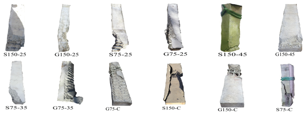
Figure 3. Overview of the 17 Samples after Testing (Elchalakani & Ma, 2017)
The experimental results demonstrated that:
We hereby propose the utilization of an analytical computer model of the concrete column, incorporating solid and linear elements available in the ANSYS Workbench 2022 R1 software library. The model encompasses concrete, longitudinal, and transverse reinforcement bars, as well as end support slabs at both ends. It is imperative to note that the model accounts for the non-linear behavior of both concrete and reinforcement.
The following elements from the ANSYS Workbench 2022 R1 library were used to represent the proposed model:
These elements are utilized. The representation will be utilized to model the concrete element, the three-dimensional support plates, and the reinforcement. The column and support plates will be fully represented and supported. The specialized instruction will also be employed to convert the volumes into unified blocks, that is, the common surface between the two volumes (column and plates). This configuration facilitates the transfer of loads from the upper support plate to the support points located on the lower support plate.
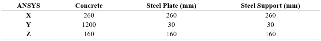
The dimensions adopted for the representation of the column, in conjunction with the plates utilized for the support process and the loads, are specified in Table 4.
Table 4. Dimensions of the Concrete Element and the Upper and Lower Support Plates.
The longitudinal and transverse reinforcement bars were incorporated as a three-dimensional element (Link180), whereby the reinforcement is delineated as a line connecting the concrete nodes, thereby ensuring the convergence of these nodes between the concrete and the reinforcement bars.
Initially, the volumetric elements, namely the concrete element and the support plates, were allocated. The finite element method was selected for the division of the volumes into cubes, a method that divides the concrete element and the support plates into sections of equal length for each dimension, as illustrated in Figure 4. Subsequently, the division command is allocated to the volumes based on their respective division lengths.
The conditions for simple support were achieved by allowing the end plates to rotate around the plate axis, as the end nodes of the upper and lower plates connected with their corresponding end nodes of the column.
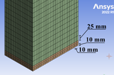
Figure 4. Meshing Strategy of RC Column.
The load was applied as a transition to the upper plate (central load case) in Figure 5 and to a group of nodes in the upper plate (eccentric load case) in Figure 6. These transitions were away from the axis of the column section at an eccentricity mentioned in Table 2. This is consistent with the experimental study and is consistent with the proposed computer model. This transition occurs in a gradual, nonlinear, and static manner.
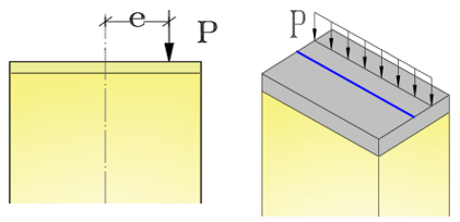
Figure 5. Application of Eccentricity Load Support of the Proposed Model.
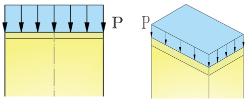
Figure 6. Application of Axial Load and Support of the Proposed Model.
In the analysis of this nonlinear static simulation, the solution is found to be contingent upon the loading history. The applied transition was divided into a single load step, which was further subdivided into substeps. The solution is terminated at the conclusion of the process. The model’s stiffness matrix was adjusted to reflect nonlinear changes in the structure’s stiffness prior to advancing to the subsequent time step. ANSYS employs the Newton–Raphson response iteration method to update the model’s stiffness. Figure 7 shows the computer model components.
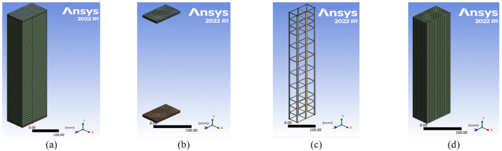
Figure 7. The Components of the Finite Element Computer Model of the Proposed Composite Column; (a): Concrete Column Model without Supports; (b): Longitudinal and Transverse Reinforcement; (c): Column Model with Support Plates; (d): Final Column Model.
The researchers proposed a concrete stress-strain curve based on mathematical equations (Figure 8), which is considered by researchers Popovics and Thorenfeldt and is used for concrete stresses ranging from 15 to 125 megapascals (MPa) (Heidarzadeh, 2022).
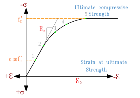
Figure 8. Typical Concrete Stress-Strain Diagram (Yun & Gardner, 2017)
The correspondence between \(f_c \) and \(\varepsilon_c\) in (Equation 1):
\[ \frac{f_c}{f_c'} = \frac{n\left(\frac{\varepsilon_c}{\varepsilon_0}\right)} {n - 1 + \left(\frac{\varepsilon_c}{\varepsilon_0}\right)^{nk}} \tag{1} \]
Where:
\[ E'_c = \frac{f'_c}{\varepsilon_0} \]
\( k \): A coefficient relating to the stress–strain diagram.
\[ n = 0.8 + (\frac{f'_c}{2500}) \tag{2} \]
Where \( f'_c \) is in psi. For \(\varepsilon_c/\varepsilon_0 \leq 1.0\): \[ k = 1.0 \tag{3} \]
And for \(\varepsilon_c/\varepsilon_0 > 1.0\): \[ k = 0.67 + (\frac{f'_c}{9000}) ≥1.0 \; \text{psi} \tag{4} \]
If \( n, f'_c, \) and \( E_c \) are known, the strain at peak stress can be computed from: \[ \varepsilon_0 = \frac{f'_c}{E_c} (\frac{n}{n-1}) \tag{5} \]
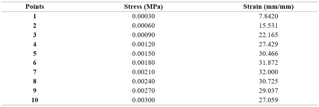
Table 5. Concrete Stress-Strain Diagram
The steel material properties employed in our model manifest elastic-plastic behavior, exhibiting a Poisson ratio of 0.3.
The stress-strain diagrams of the steel material utilized for longitudinal and transverse reinforcements were adopted based on ANSYS Workbench 2022 R1 (Figure 9).
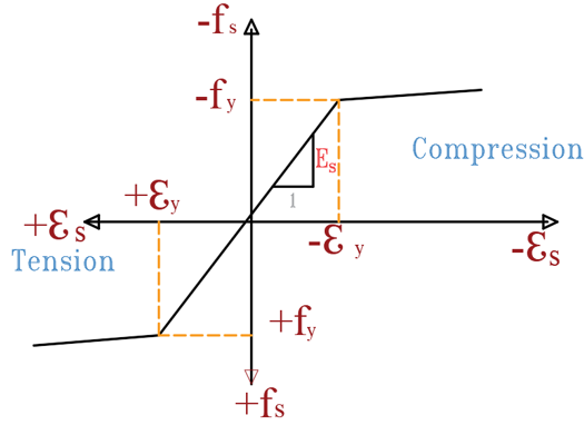
Figure 9. Strain Curve for the Steel Reinforcement (Heidarzadeh, 2022; Tao et al., 2013)
The yield strength and elasticity modulus were selected to align with the experimental research previously presented (Elchalakani & Ma, 2017), ensuring that the computational model corresponds to the experimentally studied model for comparison.
Properties of FRP Reinforcement Bars (Longitudinal and Transverse)
These fibers exhibit unidirectional behavior, characterized by linear elasticity from the onset of loading to failure. At this stage, a sequential rupture of fibers occurs, leading to complete failure. As demonstrated in Figure 10, the fibers exhibit no plastic behavior, which indicates an absence of early warning signals pertaining to structural element failure (Mohamed et al., 2014).
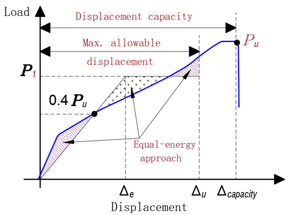
Figure 10. Typical load-displacement diagram for concrete members reinforced with polymer bars (Mohamed et al., 2014).
The proposed computer model incorporates the behavior of the polymer, and its specifications are analogous to those adopted for calibration in experimental research (Elchalakani & Ma, 2017).
Tables 6 and 7 offer a synopsis of the findings from both the experimental and analytical studies.
A comparison was made of the failure loads of samples from both the analytical study, which utilized ANSYS Workbench 2022 R1, and the experimental study, which was based on breaking the sample in the laboratory (Table 6).
Table 6. Comparison of Collapse Load Values Between the Experimental Results and the Proposed Computer Model
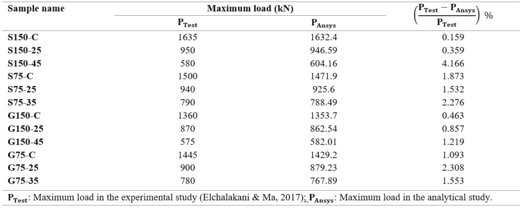
The collapse load of sample G150-C was found to be less than that of sample G75-C. This discrepancy can be attributed to the differing causes of collapse for each sample. Specifically, the collapse of sample G150-C occurred due to bending of the longitudinal reinforcement, while sample G75-C experienced rupture of the transverse reinforcement.
The collapse load of sample S150-C was found to be greater than that of sample S75-C. This discrepancy can be attributed to the underlying reasons for each sample’s collapse. Specifically, sample S150-C succumbed to the bending of the longitudinal reinforcement and the subsequent failure of the concrete, while sample S75-C experienced collapse due to the bending of the column around the weaker column.
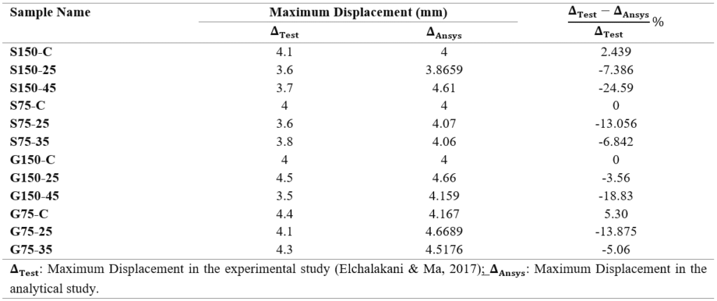
The numerical results are compared with the vertical displacements at the ultimate load for both the analytical study, which utilized ANSYS Workbench 2022 R1, and the experimental study, which was based on sample fracture in the laboratory. These findings are summarized in Table 7. The observed differences between the two studies ranged from 2.439% to 24.59%.
Steel RC demonstrated a higher load-bearing capacity by approximately 3-17% compared to polymer-reinforced bars under central loading. Additionally, under eccentric loading conditions, it exhibited the capacity to withstand an additional force ranging from 2-9% more than polymer-reinforced columns.
Table 7. Comparison of the Values of Vertical Transitions Corresponding to the Maximum Load Between the Experimental Study and the Proposed Model
As illustrated in Figure 11, the analytical study yielded results that closely mirrored the experimental findings, exhibiting a convergence ratio of approximately 98.5%.
Furthermore, it was observed that the analytical modeling yielded lower values for the ultimate load in comparison to the experimental study.
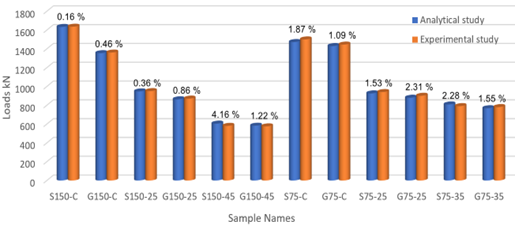
Figure 11. Comparison of Collapse Load Between Experimental and Analytical Study
The load-displacement diagrams resulting from the implementation of the proposed model in ANSYS Workbench 2022 R1 were subsequently plotted. As illustrated in Figure 12, there is a substantial convergence with the diagrams presented in the experimental study.
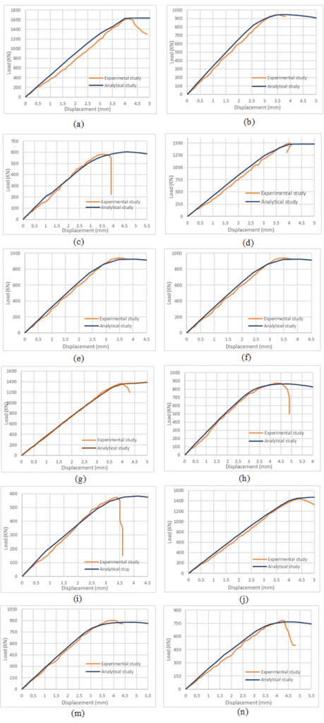
Figure 12. Comparison Between the Experimental and Analytical Study; (a): S150-C ;(b): S150-25 ;(c): S150-45 ;(d): S75-C ;(e): S75-25 ;(f): S75-35 ;(g): G150-C ;(h): G150-25 ;(i): G150-45 ;(j): G75-C ;(m): G75-25 ;(n): G75-35
The diagrams demonstrate strong convergence between the analytical and experimental models, with the exception of samples G150-45, S150-45, and S75-35. The irregularity and imbalance present in the experimental laboratory resulted in the slippage of the samples. However, the analytical study remains unaffected by this sliding process. In the analytical study, the load was 4.166% greater than in the experimental study, with a displacement difference of approximately 25%.
A computational model was developed using ANSYS Workbench 2022 R1, with the proposed model serving as a foundation for the comparison of various models for concrete column samples reinforced in three ways: reinforced bars (steel, polymer, hybrid) on combined bending.
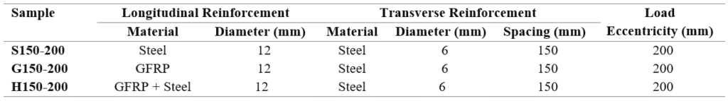
The cover of the three RC concrete columns was 25 mm thick, the height was 3,000 mm, and the cross-sections were 300 by 600 mm. The characteristics of the samples are as follows:
Model (c): The following analytical model of a concrete column, designated H150-200, is hereby presented. This finding indicates that the specimen is longitudinally hybrid reinforced (50% steel bars, glass fiber reinforced polymer bars) of the letter (H) with eight steel-reinforced bars and eight GFRP-reinforced bars, with a long-reinforced ratio of approximately 1.00%, and with transverse steel reinforcement of diameter and spacing between the bars, as illustrated in Figure 13(c).
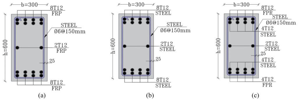
Figure 13. Cross-Section of RC Samples; (a): G150-200, (b): S150-200, (c): H150-200
The concrete was designed with a strength of 32 MPa. The three models are indistinguishable in all characteristics. These characteristics include the number and diameter of the bars, modulus of elasticity, and the stress-strain diagram of the concrete, as well as the characteristic strength of the concrete. The distinguishing factor among the three models was the reinforcement material properties of the steel and polymer bars.
The load was increased incrementally until failure with an eccentricity of 200 mm, enabling the monitoring of stress, displacement, and strain values for each loading stage.
Table 8 shows the mechanical properties of RC columns samples.
Table 8. Mechanical Properties of the Samples
Tables 9 and 10 show the GFRP-steel bars by physical properties, respectively.
Table 9. GFRP Bars by Physical Properties

Table 10. Steel Bars by Physical Properties
A comparative analysis was conducted on the standard stresses of concrete for the three-column samples prior to and following the yielding stage. The findings indicated that these stresses were comparable. (Figure 14).
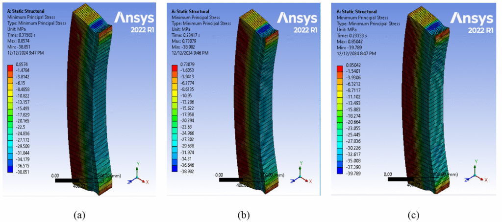
Figure 14. Normal Stresses in Concrete at Collapse Load for Samples;(a): G150-200 ;(b): H150-200 ;(a): S150-200
As illustrated in Figure 14, it was observed that the samples underwent a collapse due to the eccentric disintegration of the compressed concrete. This phenomenon occurred as the uniform stresses applied to the concrete exceeded the value of its characteristic strength. The collapse of the polymer bars, which exceeded the ultimate tensile stress value, enabled them to withstand compressive uniform stresses when exposed to eccentric loads, as depicted in Figures 15 and 16.
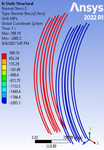
Figure 15. Normal Stresses in GFRP at Collapse Load for Sample G150-200
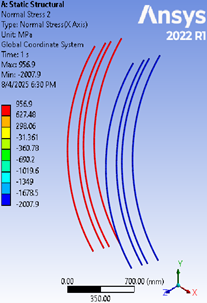
Figure 16. Normal Stresses in GFRP at Collapse Load for Sample H150-200
It was ascertained that in the two samples (S150-200, H150-200), the steel bars attained the yield stress in the area that was subject to compressive and tensile stresses, as illustrated in Figures 17 and 18.

Figure 17. Normal Stresses in Steel at Collapse Load for Sample S150-200
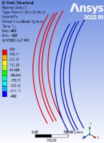
Figure 18. Normal Stresses in Steel at Collapse Load for Sample H150-200
It is important to note that the three samples under scrutiny underwent a collapse due to the disintegration of the concrete and the steel bars reaching their yield stress, with the polymer bars reaching their ultimate tensile stress.
The load-deformation curve for the three computer models in ANSYS Workbench 2022 R1 is illustrated in Figure 19.
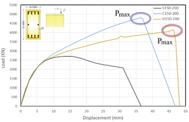
Figure 19. Load – displacement diagram for Three RC Models
A subsequent review of the load-deformation diagram of the RC column samples revealed that the reinforcing bars were affected by their physical properties. The steel columns exhibited a plasticity stage, in contrast to the polymer and hybrid columns. This outcome was attributed to the linear elastic diagram of FRP until collapse, which lacked a plasticity stage. However, the polymer bars demonstrated a substantial degree of transitional flexibility. The hybrid RC columns exhibit a transitional flexibility of approximately 7.75, which is greater than the transitional flexibility of the polymer RC columns, which is approximately 6.083.
The load-deformation diagram for the steel RC column indicates a failure load of 2728.9 kN, representing a decrease of approximately 15.82% compared to polymer-reinforced and 7.575% compared to hybrid-reinforced. Furthermore, the yield threshold exhibited distinct yet transient characteristics.
The load-displacement curve for polymer-reinforced specimens exhibited a higher capacity, approximately 8% greater than that of the hybrid-reinforced specimens. The ductility range was found to be extensive but lacked clear definition.
In this paper, an analytical computer model based on finite elements (ANSYS Workbench 2022 R1) is presented for concrete column samples that are fully reinforced with steel or polymer reinforcement. These samples were experimentally tested in a previously published international study under different loading conditions. The findings from these two studies were then calibrated to ensure the convergence of the consequences and the validity of the analytical study. In the subsequent phase of the study, the previously developed computer model was employed to analyze three concrete column specimens with distinct reinforcement types (steel, polymer, and hybrid). These specimens were subjected to a combination of bending forces. This research constitutes the inaugural investigation that undertakes an analytical examination of hybrid reinforced concrete columns under conditions of complex bending, with equal moduli of elasticity between the polymer and steel bars. The ensuing discussion will present the pivotal outcomes derived from the analytical study that employed computational modeling.
N. A. A: Conceptualization, Methodology, Software, Validation, Formal analysis, Investigation, Resources, Data curation, Writing of the original draft, Writing – review & editing.
M. B. K: Conceptualization, Resources, Writing – review & editing, Supervision.
The authors declare that they have no known competing financial interests or personal relationships that could have appeared to influence the work reported in this paper.
This research did not receive any specific grant from funding agencies in the public, commercial, or not-for-profit sectors.
No generative AI or AI-assisted technologies were used in the preparation of this manuscript.
The data that support the findings of this study are available from the corresponding author upon reasonable request.
The authors declare that there is no acknowledgement to be made.
This study did not involve human participants or animals; hence, no ethical approval was required.
Cite: ALkhalil, N. A., & Kanjo, M. B. (2025). An Analytical Study of Hybrid Reinforced Concrete Columns on Combined Bending. Steps For Civil, Constructions and Environmental Engineering, 3(1), 25-41. https://doi.org/10.61706/sccee1201193
![]() Copyright: © 2025 by the authors. Licensee Scientific Steps International Publishing Services, Dubai, UAE.
Copyright: © 2025 by the authors. Licensee Scientific Steps International Publishing Services, Dubai, UAE.
This article is an open access article distributed under the terms and conditions of the Creative Commons Attribution (CC BY) license (https://creativecommons.org/licenses/by/4.0/).


An independent academic publisher with an editorial team including many of the top researchers in the world. SSG publishes research, review, and case report articles in double-blind, peer-reviewed, open access scientific and academic journals.
Copyright © 2025 Scientific Steps International Publishing Services LLC (Dubai – United Arab Emirates)