
ISSN: 3005-8198 (online) | 3005-818X (print)
Volume 2, Issue 2 (April - June 2024) Pages 35-43
In concrete members that are subjected to bending, such as beams and slabs, the tensile and shear strength of concrete is an important property. Over the years, a lot of work has been done to try and improve these properties. It has been found that concrete’s biggest shortcoming is its weak tensile and shear strength. To improve the tensile and shear strength, different types of reinforcement, such as round bars or fibres, have been added to the concrete. The interfacial transition zone’s strength and density are improved, due to the small size and tensile strength of the incorporated nano-materials. The tensile and shear strength of concrete is the focus of this investigation with the incorporation of multi-walled carbon nano-tubes (MWCNTs) and graphite nano-fibres (GNFs) into the concrete mix. One of the limitations to the use of nano-materials in concrete mixes is the tendency of the carbon nanotubes to adhere to one another due to the formation of balls and the strong van der Waals interaction forces. Additionally, there is a lack of cohesion between the nanotubes, which can be attributed to the cost of nano-materials. However, cohesion can be increased by using gum arabic and a process called functionalization, which helps to improve the dispersion and purification process of the nano-materials.
Keywords: Tensile, Shear, Concrete, Nanomaterials, Fibres.
More or less 50% of the value of the compressive strength of concrete equals the shear strength of the concrete (Institute, 2001; Mindess, Young, & Darwin, 2003). As for the tensile strength of concrete, it has been demonstrated that the tensile strength in concrete is highly variable, ranging from 8 to 15% of the compressive strength. The variability of the tensile strength is due, in part, due to the fine cracks found throughout the concrete. More or less 10% of the value of the compressive strength of concrete equals the tensile strength of concrete (Institute, 2001). However, the tensile strength of concrete increases as the compressive strength increases, however although not at the same rate (Mindess, Young & Darwin, 2003). In compression, at moderate levels of stress, concrete can transmit stress across both the cracked and un-cracked areas in the concrete. However, when the concrete is loaded in tension, the tensile stresses cannot be transferred across a crack. Consequently, the tensile stresses are only carried by the un-cracked area of the cross-section. The tensile stresses flow around the internal cracks and voids. This produces stress concentrations at the perimeter of a void and at the tips of a crack. Thus, although the average stress in the concrete may be low the local stresses may be high enough to cause internal cracks to lengthen. Consequently, the un-cracked area diminishes in size, the stresses increase, and failure ensues rapidly (Crespi, 2006; Carbon Nanotube, 2007).
Concrete is made up of fine and course aggregates, hardened cement pastes and the interfacial transition zone and hence this heterogeneous nature gives concrete its different properties. Due to the different strengths of the different types of materials, the weaker hardened cement paste compared to the strong aggregates, contributes mostly to the concrete strength. The weak link in the paste comes from its porosity, microstructure and interfacial transition zone. Bonding between aggregate and paste also plays a role in the strength of concrete. This bond depends on the interlock between the aggregate and the cement paste. Most concretes are mixed in such a way that they inherently have a weak, porous interfacial transition zone between the cement paste and the aggregate (Zafar & Amit, 2008). Compaction of wet concrete causes the aggregate and paste to move relative to each other and increases the likelihood of the formation of the water-rich, weak zone between the aggregate and cement paste (Inc, 2006). When concrete disintegrates, fracture paths are often seen along the interface between the hydrated cement paste and the coarse aggregate particles, but it is still unknown whether this is due to the increased stresses caused by the more rigid aggregate or the inherent weakness of the interfacial zone (Zafar & Amit, 2008). The interfacial transition zone’s thickness around the aggregates is unclear. A higher tensile and shear strength can be achieved with a higher porosity. Research has shown that the dense packing of cement particles or silica fume around the aggregate creates a composite structure that can increase the strength of the concrete by up to 30% as it is very fine and thus helps to densify the interfacial transition zone (Zafar & Amit, 2008; Inc, 2006). An increase in the cement-aggregate interfacial bond strength can force the fracture path to pass through the aggregate rather than the interfacial zone. This increases both the fracture toughness and the brittleness of the concrete.
It is postulated that the toughness of concrete can be increased due to the elastic behaviour of carbon nanotubes (CNTs) and their ability to absorb energy (Nalwa, 2000). Smith, 2006 suggested that nanoparticles fill the voids between cement grains and improve the structure of the interfacial transition zone, resulting in a better bond between aggregates and cement paste. Furthermore, Smith (Smith, 2006) postulated that nano-particles Promote the formation of small crystals such as Ca(OH)2 and small groups of calcium silicate hydrate gel, improve the toughness, shear, tensile and flexural strength of cement-based materials by inhibiting cracking and interlocking effects, improve the segregation resistance and workability of the system by making the liquid phase more viscous and thus helping to suspend the cement grains and aggregates, and act as a nucleating agent to promote the crystallization of cement hydrates, thereby increasing the rate of hydration. Mitsui (Mitsui & Maso, 1992) investigated the relationship between the mechanical properties and the microstructure of the interfacial transitional zone and found that the interfacial parameters were significantly improved by incorporating silica fume into the matrix and pre-treating the aggregate by coating it with a cement slurry containing silica fume (Terry & Baker, 1998). As CNTs are much finer than silica fume, functionalizing the aggregate and coating it with CNTs may further improve the interfacial transition zone. However, Maso (Maso, 2014) found that attempting to improve the interfacial transition zone characteristics can make the concrete more brittle (Inc, 2006).
Thus, the tensile and shear strength of concrete are the focus of this investigation with the incorporation of multi-walled carbon nano-tubes (MWCNTs) and graphite nano-fibres (GNFs) into the concrete mix. This has been done to try and establish whether there is an enhancement of concrete properties and a subsequent reduction in shear reinforcement. It is expected that the addition of the nano-materials will have positive effects of the strength and porosity of the interfacial zone of the concrete due to the fact that silica fume has achieved this objective. Moreso, it is expected that the finer nano-materials will do so even more than silica fumes.
Figure 1 shows the stacked-on top of each other hexagonal or honeycomb patterns of these fibres which consist of carbon atoms arranged as sheets. These sheets are weakly bonded together, but are very strong, flexible and stable and is predominantly made up of sp2 bonds (Crespi, 2006; Carbon Nanotube, 2007). Other properties of the fibres include their small diameter(1-2nm), big length-to-diameter ratio (>10000) and strength (approximately 300 the strength of steel. Limitations to use of these fibres in concrete mixes is the tendency of the fibres to adhere to one another due to the formation of balls and the strong van der Waals interaction forces, lack of cohesion between fibres and the concrete materials and lastly the expensive nature of producing these fibres on a large scale. To try and overcome the limitation of cohesion gum Arabic (GA) was used. To aid the dispersion and purification of the fibres, a functionalization process was used.
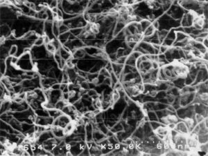
Figure 1. Scanning Electron Microscope Image of Graphite Nano-Fibres (Zafar & Amit, 2008)
Single-walled or multi-walled carbon nano-tubes (CNT’s) are allotropes of carbon. A single-walled carbon nanotube (SWCNT) consists of a single graphite sheet in the form of a long thin tube as shown in Figure 2. Properties of the fibres include a small diameter (1-2 nm) and big length-to-diamter ratio (>10000) (Carbon Nanotube, 2007). The difference for SWMCNT and multi-walled carbon nano-tubes (MWCNTs) is that it is made up of multiple layers of graphite sheets to form the tub (Inc, 2006). These tubes are closed at both ends (Nalwa, 2000). CNTs have very promising mechanical properties but has not been standardized due to the difficult nature in testing nano-materials. These fibres are predominantly made up of sp2-hybridized C-C covalent bonds. They have more or less the same mechanical properties as GNF’s. The strength of the sp3 bonds in diamonds are put to shame by the strength of these fibres (approximately 150GPa, stronger than the strongest steel) (Terry & Baker, 1998; Inc, 2006). With their strong tensile strength (150GPa) and Young’s modulus (1054GPa), these fibres have a very weak compression, torsional and flexural strength. This weakness is due to their hollow nature and high aspect ratio (ratio of longer to shorter dimension). The tubes are very flexible and cannot break and tend to form kinked ridges. Unfortunately, because carbon nanotubes are insoluble in many liquids, such as water, polymer resins and most solvents, they tend to agglomerate, making them difficult to disperse in the liquid. This property is detrimental to increasing the mechanical strength of the materials in which the nanotubes are placed, as the distribution of the nanotubes is uneven (Institute, 2001). In addition, there is a lack of cohesion between the nanotubes and the bulk matrix material. GA was used as a dispersant.
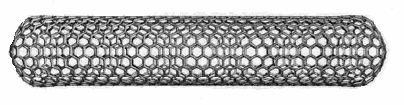
Figure 2. Closed Single-Walled Carbon Nano-Tube (Terry & Baker, 1998)
Before GNFs and MWCNTs can be incorporated into the concrete mix, it is important that the nano-materials are functionalized. For GNFs, the functionalization process helps to remove any impurities and disperse the nano-fibers, but for MWCNTs, which are supplied clean, functionalization only helps to disperse the MWCNTs in the concrete mix. An 85% reduction in strength can be caused by nano-fibres due to impurities. A further reduction in strength can be attributed to low cohesion between the fibres and concrete matrix. The for-mentioned causes the fibre to pull out and slip (Standards S. A., 2006b). Literature suggests that the smooth fibre surfaces and small diameters which cause this problem can be improved via functionalization of the fibres or aggregates (Institute, 2001). The fibres were weighed and dissolved in 80ml of acid (3:1 ratio of sulphuric to nitric acid). This was done to try and remove impurities and help with dispersion. A fume hood was used to reflux the mixture at 55°C for 24 hours, shown in Figure 3. The mixture was allowed to cool to room temperature. Then 2.5 liters of distilled water was then added to the functionalized nano-materials (10-20 g). To achieve a pH of 5-7 (neutral acidity), the mixture was filtered through 125 nm standard/normal filter paper and washed with more distilled water. A pump was then used to dry the mixture in a vacuum. They were then kept dry and sealed until use. The functionalization process leaves the nano-materials in flake-like structures. These had to be crushed before they could be used in the concrete mix. However, the functionalization process reduces the yield of MWCNTs. It is therefore not possible to functionalize an exact quantity of 86 grams of MWCNTs. For the purposes of this project study, 160 grams of MWCNTs were ordered and functionalized. The yield of MWCNTs is determined by analysing the mass of MWCNTs before and after functionalization. It was found that the percentage yield for the process was approximately 75%. The amount of cement was not reduced to accommodate the MWCNTs as this could have resulted in a significant loss of strength.
Standardized methods were used to cast, create a mix design, batch the concrete, performing slump tests, pour the concrete into moulds, 24 hours curing and testing the 28-day old specimens. The C & CI method was used for the mix designs (Addis & Owens, 2001). Sample series 1 was a standard mix with no inclusions. Sample series had gum Arabic (GA) as an inclusion to the mix. Sample series 3 had GA and functionalized GNFs/MWCNTs as inclusions to the mix. For improved cohesion between fibres and cement paste, water mixed with GA was added. The downside to adding GA is reduced concrete strength and workability. Workability was bettered by changing the water: cement ratio (0.73:1 to 5:1). The functionalized flaky nano fibres were grinded and added to the mix. SANS 5861-3:2006 (Standards S. A., 2006a) was used a guideline to cure the samples. SANS 5862-1:2006 (Standards S. A., 2006b) was used a guideline to perform the slump test of the concrete mixes. Table 1 shows these results.

Figure 3. Functionalization Process, (a) Mixing of The Acids, (b) Nano-Materials, (c) Refluxing of The Nano-Materials, (d) Filtering Process
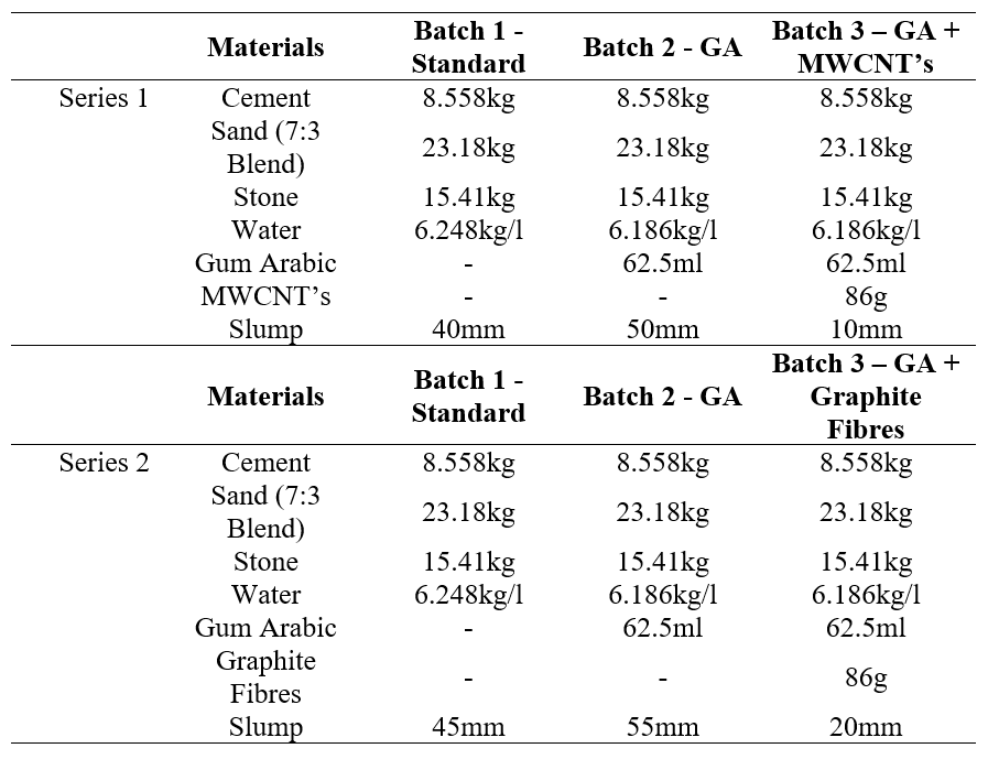
Table 1. Concrete Mix Design for Each Series
There are no standard methods for directly testing the tensile strength of concrete. This is because it is extremely difficult to set up a test in which the concrete specimens are tested purely for tensile strength. Because of these difficulties, the tensile strength of concrete is usually determined by indirect means, such as the tensile splitting test (Standards B. E., BS EN 12390-6:2009) or the flexural strength test (Standards B. E., BS EN 12390-5:2019). In these tests, a dog-bone mould was used to determine the tensile strength of the specimen. In terms of mould size, the length is 80 mm, the central neck is 25 mm, the largest width is 50 mm, and the height of the mould is 20 mm. The main problem in testing these specimens was to eliminate the moments caused by misalignment of the specimens. Therefore, the specimen had to be centered and aligned vertically in the Instron 1195 machine as shown in Figure 4. The second disadvantage of performing a direct tensile test is the presence of secondary stresses that begin to build up when the grips are applied to the ends of the specimen. These secondary stresses reduce the chances of obtaining the true tensile strength of the specimen (Institute, 2001; Nilson, 2022; Popovics, 1998). The specimens were pulled at a rate of 1 mm per minute. Tensile strength was calculated from the maximum force recorded by the machine and the area of the neck. As expected, failure of the dog-bone specimens occurred at the neck of the specimen.
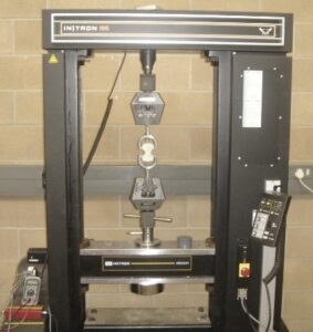
Figure 4. Tensile Test Setup
Bending tension and compression acts together with shear stresses. Shear stress is never found alone in concrete structures. Shear stress is very difficult to measure by itself. From literature the following have been tried to measure shear stress: short span beams and placing loads close to the support points. A slightly higher shear strength than the tensile strength was found, and some tests showed the shear strength to be 50-90% the compressive strength, because either tensile or compressive stresses may have been acting on the specimens (Inc, 2006; Popovics, 1998). Figure 5 shows the new mould designed to test the shear strength of the concrete specimens (Mac Gregor & Wright, 2011). Similar to concrete cubes the specimens were crushed at a rate of 100 kN per minute. Figure 6(a) shows the placement and vertically aligned specimens in the Avery Davison crusher. The specimens were tested to failure in shear as shown in Figure 6(b) – the shear failure plane.
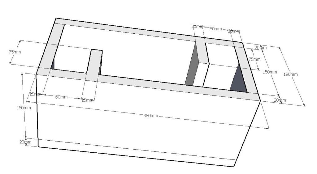
Figure 5. Shear Mould Dimensions
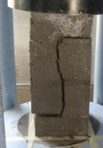
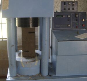
Figure 6. Shear Test Setup and Shear Zone, (a) Test Setup, (b) Direst Shear Failure
Table 2, Figures 7 and 8 showed the results obtained for this research. These results show the relative sample strength compared to the control samples. From literature, which stated that the addition of GA had a positive effect on the strength of the concrete (Saez de Ibarra, Gaitero, & Campillo, 2003), it was found that the effects of GA addition had a negative impact on the results of the shear strength.
A reduction of 5% in the tensile strength of series 1 and 2 (when GA is added) is shown in Table 2 and Figure 7. With the addition of GA and MWCNTs to series 1, the final tensile strength of the concrete was very close to the control samples. Thus, the gum arabic showed a 5% reduction in tensile strength, but the final tensile strength showed a 4.5% increase in tensile strength when the MWCNT’s was added. In series 2, the GA and GNFs only showed an increase of 2% when the fibres were added.
Table 2 and Figure 8 showed that by adding GA to series 1 and 2, the strength in shear was reduced by 5-6%. For series 1, when MWCNTs were also added to the mix, it showed an increase of 6%. Effectively this means a 11-12% increase by adding MWCNTs, because of the physical cylindrical shape of the nanomaterials that is a much stiffer and stronger elastic rod due to a rolling process. For series 2, when GNFs were also added to the mix, it showed a reduction of 15%. Effectively this means a 9-10% reduction by adding GNFs, because of the flat shape and the soft and slippery nature of graphite.
Table 2. Tensile and Shear Strength
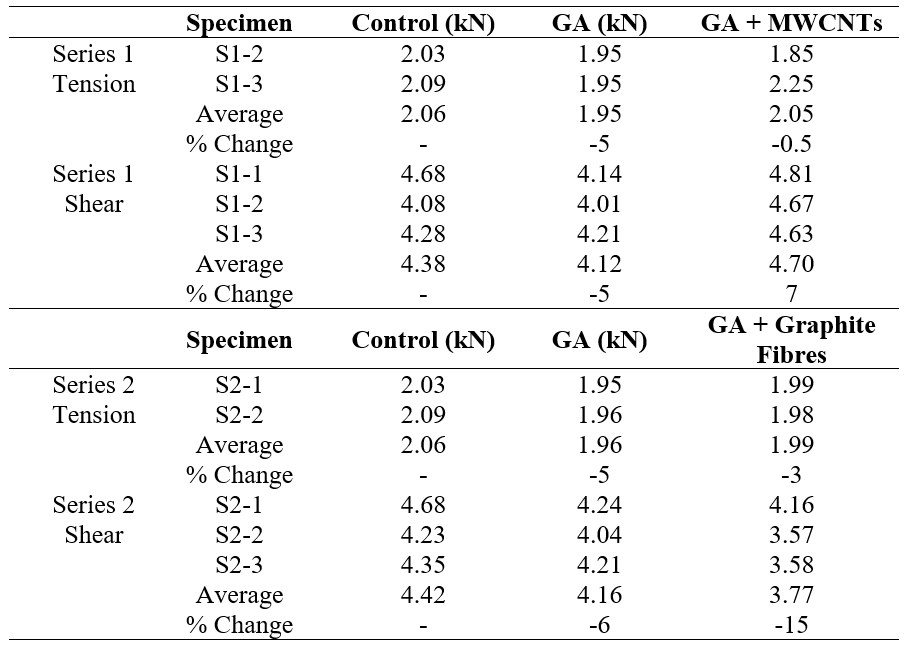
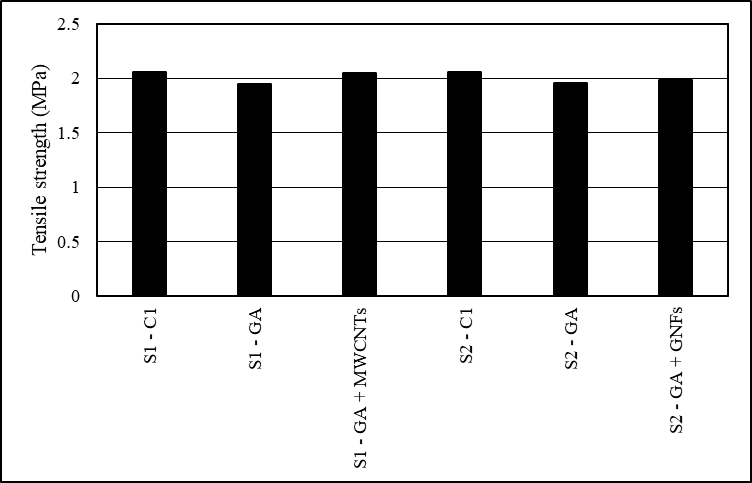
Figure 7. Average Tensile Strength of The Specimens
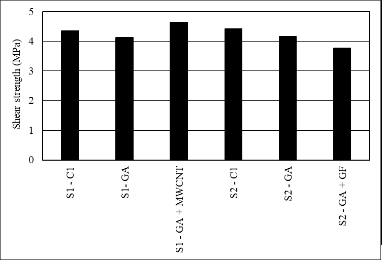
Figure 8. Average Shear Strength of The Specimens
When nano-materials were incorporated into the concrete at a level of 1% by weight, a small increase in tensile strength was observed. The increase was more pronounced in the samples with MWCNTs than with GNFs. MWCNTs also increased the shear strength of the concrete, but GNFs did not. This increase can be attributed to the bridging ability of the nano-materials over the micro-cracks found in the mortar-aggregate interface and to the physical properties of the nano-materials, which are much stiffer and stronger compared to the softer graphene sheet of GNFs. GNFs concrete probably showed a decrease in shear strength due to its soft and slippery properties. In all series, the use of GA as a dispersant resulted in a decrease in the strength of the concrete. This suggests that alternative dispersing techniques should be investigated. It may not be economical to use the two nano-materials investigated, as despite the influence of GA, they do not seem to increase the tensile and shear strength of concrete much.
P.VT: Conceptualization, Methodology, Validation, Formal analysis, Investigation, Resources, Data curation, Writing of the original draft.
The authors declare that they have no known competing financial interests or personal relationships that could have appeared to influence the work reported in this paper.
This research did not receive any specific grant from funding agencies in the public, commercial, or not-for-profit sectors.
No generative AI or AI-assisted technologies were used in the preparation of this manuscript.
The data that support the findings of this study are available from the corresponding author upon reasonable request
The authors declare that there is no acknowledgement to be made.
This study did not involve human participants or animals; hence, no ethical approval was required.
Cite: van Tonder, P. (2024). Tensile and Shear Response of Concrete with Nanomaterials. Steps For Civil, Constructions and Environmental Engineering, 2(2), 35–43. https://doi.org/10.61706/sccee120118
![]() Copyright: © 2024 by the authors. Licensee Scientific Steps International Publishing Services, Dubai, UAE.
Copyright: © 2024 by the authors. Licensee Scientific Steps International Publishing Services, Dubai, UAE.
This article is an open access article distributed under the terms and conditions of the Creative Commons Attribution (CC BY) license (https://creativecommons.org/licenses/by/4.0/).


An independent academic publisher with an editorial team including many of the top researchers in the world. SSG publishes research, review, and case report articles in double-blind, peer-reviewed, open access scientific and academic journals.
Copyright © 2025 Scientific Steps International Publishing Services LLC (Dubai – United Arab Emirates)