
ISSN: 3005-8198 (online) | 3005-818X (print)
Volume 3, Issue 4 (October - December 2025) Pages 30-51
1 Faculty of Civil Engineering, Cracow University of Technology, Poland.
2 Faculty of Civil Engineering, AL-Wataniya Private University, Syria.
Advancements in construction materials have been a subject of considerable interest, with a particular focus on the use of carbon fiber-reinforced polymers (CFRP) as a means of enhancing the structural performance of various structures when utilized in an optimal manner. The objective of this research is to design and analyze reinforced concrete beam sections that incorporate concrete, steel, CFRP strips, and metal tubes. The study is contingent upon the high compressive strength of concrete confined within metal tubes and the tensile strength of CFRP strips. Concurrently, transverse and longitudinal reinforcement contribute to shear and flexural resistance. A total of twelve beam models were subjected to analysis, including three conventional reinforced concrete beams and nine composite sections that incorporated CFRP and metal tubes. The findings indicated a substantial enhancement in moment capacity, with the utilization of CFRP resulting in an average increase of 82.76%, metal tubes leading to an increase of 628.27%, and the combination of both contributing to an average increase of 791.3%. The study underscores the efficacy of these techniques in the design and strengthening phases, providing pragmatic guidelines for prospective applications.
Keywords: Composite Section, CFRP, Longitudinal Reinforcement, Metal, Strips, Transverse Reinforcement.
In recent decades, the construction industry has witnessed significant advancements in materials and methodologies employed to enhance existing structures and their functional capabilities. One of the most novel types of materials utilized is fiber-reinforced polymers (FRP), which possess traits such as very high flexibility and strength compared to traditional materials, such as steel. Fiber-reinforced polymer (FRP) materials encompass carbon fiber (CFRP), fiberglass (GFRP), and aramid fiber. These materials have been utilized in numerous structural applications to augment the tensile strength of concrete elements. Tensile stress, being one of the most prevalent forms of stress, hinders the effectiveness of concrete as a material. Concrete is adept in compression but exhibits weakness in tension.
The enthusiasm associated with FRP is also linked to its many other benefits, including its relatively high tensile strength and low weight compared to some steel, along with high resistance to corrosion from the environment. This makes it especially well-suited for extreme conditions, such as structures routinely exposed to moisture or chemical conditions. Additionally, FRP panels, which are available in various geometries, can be readily installed directly on concrete surfaces, thereby promoting reinforcement and restoration activities.
The significance of experimental and analytical studies on beam reinforcement using FRP is multifaceted and warrants further examination. For instance, scientific studies have demonstrated that the incorporation of CFRP strips to the underside of metal beams (I-beams) results in a substantial enhancement of the load-bearing capacity of the beams. This finding is supported by research conducted by Schnerch et al. (2005, 2006) and Shen et al. (2023). This phenomenon occurs because CFRP enhances the tensile strength of the section in combination with the strength of the steel itself. Consequently, the load is distributed more effectively. Research has demonstrated that the beam’s stiffness during the plastic stage, a pivotal indicator of enhanced dynamic performance, has shown increases of 25%. Stiffness, otherwise referred to as structural performance, is an indicator of the beam’s capacity to withstand substantial loads (with repetition). For instance, a study that integrated field tests and analytical simulations substantiated the efficacy of this reinforcement type in enhancing the bending performance of concrete beams (Al-Saidy et al., 2007; Schnerch et al., 2005, 2006; Shen et al., 2023).
These findings substantiate the predominance of CFRP in numerous engineering applications, particularly in the context of structures of paramount importance or under variable and multi-source loading conditions.
A comparison of the performance of CFRP with other types of FRP and with steel is important to enrich research and study with these comparisons and previous ones. A recent study demonstrated that CFRP exhibited superior enhancement in flexural strength when compared with GFRP. CFRP exhibited an average increase of 65.9% in flexural strength, while GFRP demonstrated an increase of approximately 44%. This discrepancy can be attributed to the distinct mechanical properties of carbon fibers, which are renowned for their exceptional tensile strength, durability, and performance at varied temperatures. Additionally, these fibers exhibit enhanced adhesion to concrete surfaces (Tarigan et al., 2018). In addition to performance, factors such as cost, ease of installation, and weight must be considered when selecting an FRP type for a given application. For instance, carbon fiber-reinforced plastic (CFRP) is generally considered to offer superior performance, yet it is also more costly than glass fiber-reinforced plastic (GFRP). Consequently, engineers must strike a balance between economic viability and performance in their designs.
The study of composite mechanisms has led to the development of methods for reinforcing beams using both fiber-reinforced polymer (FRP) and metal elements. A primary focus of the research is to use FRP reinforcement technology with prestressed external metal members, such as steel angles or tubes, to enhance structural performance. This approach has been demonstrated to enhance multiple properties concurrently, including bending resistance, stiffness, and ultimate load capability. For instance, the incorporation of a CFRP panel at the base of a beam, in conjunction with an externally prestressed steel angle, led to an enhancement in the beam’s resistance to larger bending loads. This augmentation in resistance enabled the beam to support increased bending loads with greater stiffness, while concurrently delaying the onset of crack formation. Additionally, it increased the beam’s resistance to short and hazardous loads (Jiang et al., 2021). This mechanism is particularly effective for structures that necessitate comprehensive enhancement while preserving deadweight, and for which a complete restructuring or replacement is not feasible.
A comprehensive review of research indicates that FRP techniques are employed in numerous projects for the maintenance and renovation of existing structures. The primary advantages of these techniques include their rapid installation, minimal disruption during construction, and the capacity to enhance performance within a brief timeframe. These materials are also employed in new constructions to enhance beam flexural capacity from the outset of design, allowing for the use of smaller, lighter sections without compromising structural safety (Li, 2023).
The utilization of these materials to modify beams has been demonstrated to reduce the necessity for costly demolition and reconstruction processes. This approach offers engineers a wider range of implementation and design options and is often more cost-effective than using beams composed exclusively of steel.
A substantial body of research has demonstrated that the method of fixing FRP panels is a critical factor in achieving effective and sustainable reinforcement outcomes. The utilization of mechanical fasteners or external bonding with fixing screws constitutes a conventional and empirically validated approach. Nevertheless, this method is susceptible to complications, including separation and corrosion (Faney & Hema Priya, 2024).
The concept of near-surface mounting (NSM) has emerged as a novel and distinctive method that facilitates enhanced interaction between the reinforced plate and the concrete. This method involves the placement of FRP strips within grooves that are carved into the surface of the concrete element. The efficacy of this technology in enhancing shear resistance and optimizing the performance of beams has been demonstrated. Additionally, it mitigates the risk of separation caused by environmental and load fluctuations. A substantial body of research has examined this technology as a sophisticated and promising approach to enhancing the durability of buildings (Faney & Hema Priya, 2024).
Engineers continue to express concerns regarding the impact of CFRP on the compressive strength and durability of structural elements. Compressive strength represents a significant concern in the utilization of FRP, given that concrete is predominantly subjected to compressive stress. However, studies have demonstrated that CFRP does not compromise the residual compressive strength of the element, even under conditions of repeated loading cycles and elevated loads. Consequently, the implementation of CFRP reinforcement in reinforcing beams has been demonstrated to augment the concrete’s compressive strength, thereby enhancing its overall behavior (Launay et al., 2022).
A study of strategies for using specially shaped metal plates with FRP was conducted. The integration of Z-shaped metal plates and L-shaped bottom plates, affixed to FRP plates using high-strength screws, has been demonstrated to significantly augment the flexural capacity and stiffness capability of existing reinforced concrete beams. This method facilitates a more uniform distribution of the load, thereby preventing premature splitting and enhancing the effectiveness of the structures.
The study’s findings indicated that the robust bond between the metal plates and concrete enhances the resistance to both dynamic and static loads, particularly in beams subjected to combined and variable loads (Ro et al., 2024).
Samples modified with these plates exhibited a maximum load that was 1.6 times greater than the maximum load of unmodified beams. Moreover, the integration of interconnected steel plates has been demonstrated to enhance load capacity by approximately 25%, in comparison with individual plates. The load application point and unit size have been demonstrated to have a substantial impact on the performance of standard steel plates.
Hybrid reinforcement of beams, which integrates fiber-reinforced polymer (FRP) and reinforcement bars, exhibits a range of advantages and disadvantages. A comparative study demonstrated that beams reinforced with a hybrid reinforcement scheme of steel bars and FRP bars (particularly CFRP) exhibited elastic behavior and greater load-carrying capacity. Hybrid reinforcement schemes allow for the optimal utilization of the properties of both materials: the elasticity and strength of steel, as well as the lightness and stiffness of CFRP (Ge et al., 2023).
The high costs associated with hybrid reinforcement and the additional effort required to ensure optimal design quality and harmonize different materials may pose potential disadvantages. It is imperative to allocate particular attention to the areas of overlap at connections and the bonding of materials. This is crucial to mitigate the risk of separation and/or premature failure. A plethora of studies have noted the failure of experimental models due to the loss of cohesion between the added reinforcement elements and the structural material of the reinforced element. For instance, Castori et al. (2025) documented the collapse of titanium rods used as external reinforcement for concrete beams. Similarly, Kholil and Ahmed (2026) reported the collapse of reinforcement based on strengthening the beam section by adding a steel plate fixed to the underside of the beam as a result of its separation from the concrete and loss of cohesion. Finally, Alkhateeb and Hejazi (2024) and Codina et al. (2025) documented the collapse of the mechanical fastening of externally added carbon fiber strips at the ends of the beam.
Xiao et al. (2025) propose novel methodologies for reinforcing reinforced concrete (RC) beams. These methodologies involve the external bonding of a composite plate of FESP to a concrete groove, thereby enhancing the structural integrity of the beams. In order to comprehend the bending behavior of the reinforced beams, four-point bending tests were conducted, and the influence of key factors was analyzed. To this end, theoretical calculations were developed to estimate the surface stresses at the edges of the FESP. The optimal thickness for the steel plate was recommended. In the event that the steel plate is of insufficient thickness, the enhancement in the stiffness of the reinforced beam is constrained. Conversely, when the coating is excessively thick, the surface stress at the edge of the plate will exceed the bonding strength provided by the groove and the adhesive layer, leading to ultimate bond failure.
In the study conducted by Chen et al. (2024), a novel methodology was proposed for the application of pre-stress to the carbon fiber strip prior to its placement within a metal tube. This approach was predicated on the premise that the metal tube would serve to stabilize the ends of the strip following the application of pre-stress.
As stated by Talahmeh et al. (2025), the objective of the research was to reinforce an entire building with carbon fiber strips and concrete cladding. The technique demonstrated a successful transfer of plastic hinges and a delay in their occurrence, thereby supporting the direction of future research. Specifically, this research will study the effect of reinforcement techniques on the entire building, with a focus on the transfer of plastic hinges from columns to beams and the control of the sequence of element collapse. The objective is to ensure a safe collapse pattern that protects the lives of residents in reinforced concrete buildings.
While significant advancements have been made in methods of reinforcing beams with FRP and metal elements, metal cladding has not received a comparable level of research attention as column reinforcement methods. This study addresses this research gap by examining the interactions and mechanical influences of metal cladding and CFRP strips on beam performance, both separately and in combination.
The present study investigates the use of metal tubes and CFRP strips in new construction and the strengthening of existing structures. The enhancement in bending capacity for each category of reinforcement, in conjunction with the efficacy of the integrated application of these techniques, is subjected to rigorous evaluation. Furthermore, counsel is dispensed during the design and construction phases, as well as in the reinforcement of existing edifices, with a focus on both concepts and techniques.
This enhances our understanding of how to improve beam resistance and understand complex failure mechanisms, contributing to the development of more effective and safer reinforcement solutions, both in new and existing structures.
The study’s limitations are manifold, including but not limited to the following: the potential for CFRP delamination, local buckling of the metal box, concrete crushing, and local yielding of steel. Consequently, the present study concentrated on examining the moment capacity at the section level. The selection of bending behavior was motivated by its significance in large-span structures, wherein the bending moment exhibits a quadratic increase with span, as dictated by established structural relationships. The investigation did not encompass a comprehensive analysis of failure mechanisms or the study of shear, ductility, and cracking behavior. These issues will be addressed in subsequent research, which will be complementary to this work. This subsequent research will include analytical and experimental models of complete awards. These mechanisms will be addressed in detail through subsequent analytical and experimental studies. The objective of these studies is twofold: first, to determine the safety limits of the proposed reinforcement techniques, and second, to ascertain the practical applications of these techniques. In addition, these studies will verify the validity of the current analytical studies.
This research is firmly rooted in analytical and numerical studies, which seek to examine the structural behavior of reinforced concrete bridge sections at the section level. The objective is to ascertain the impact of various reinforcement techniques on the moment capacity. Due to the comprehensiveness of the study in terms of the multiplicity of reinforcement techniques and the different dimensions of the sections, numerical analysis was adopted as a first step to select the most efficient structural arrangements.
The present study is predicated on an analytical investigation of twelve geometric models that vary in terms of dimensions and materials utilized in their design. The objective of this investigation is to analyze the effect of material properties and design parameters on the overall performance of the models.
In this study, the physical, mechanical, and design properties of a set of fundamental construction materials were entered into the engineering program (Section Designer) used to analyze and design sections. The objective of this entry is to ensure the accuracy of numerical modeling and the validity of design results. The materials examined encompass the following categories: concrete, carbon fiber-reinforced polymers (CFRP), steel of rectangular tubes, and steel of rebars.
In order to ensure a fair and direct comparison between different reinforcement techniques, constant values for material properties were adopted in all models studied. The objective of this procedure is to isolate the effect of the reinforcement type itself, without introducing additional variables. Standard stress-strain models for concrete, steel, and CFRP strips were adopted in accordance with the requirements of ACI Committee 318 (2014) and the program’s definition. It has been noted that the study of variability in physical properties and the effect of uncertainty will be addressed in subsequent design and experimental research.
Concrete is defined in the program as a homogeneous, non-linear material with characteristic compressive behavior and limited tensile strength. The concrete class is determined by the characteristic strength (f’c) employed in the design, and the physical properties of concrete are specified in Table 1.
It is important to note that the density utilized in this study corresponds to that of normal-weight concrete, with a compressive strength that reflects a balanced and realistic choice between mechanical performance and structural weight. As demonstrated in Table 2, the mechanical properties of concrete were thoroughly examined and characterized.
| Property | Value | Unit |
|---|---|---|
| Weight per Unit Volume | 23.5 | kN/m³ |
| Mass per Unit Volume | 2402 | kg/m³ |
| Property | Value | Unit |
|---|---|---|
| Modulus of elasticity | 24855 | MPa |
| Poisson's ratio | 0.2 | - |
| Shear modulus | 10356 | MPa |
Carbon fiber-reinforced polymers (CFRP) are a class of composite materials that consist of high-strength carbon fibers bonded to a polymer matrix. The utilization of carbon fiber-reinforced polymers (CFRP) is predominantly focused on structural reinforcement and restoration. The physical properties of these polymers are delineated in Table 3, while the mechanical properties are enumerated in Table 4.
| Property | Value | Unit |
|---|---|---|
| Weight per Unit Volume | 16 | kN/m³ |
| Mass per Unit Volume | 1631 | kg/m³ |
| Property | Value | Unit |
|---|---|---|
| Modulus of elasticity | 165000 | MPa |
| Poisson's ratio | 0.3 | - |
| Shear modulus | 63461 | MPa |
Rectangular steel tubing is frequently utilized as structural steel in the fabrication of prefabricated sections or composite elements. The physical properties of steel tubes are specified in Table 5, and the mechanical properties of steel tubes are determined in Table 6.
| Property | Value | Unit |
|---|---|---|
| Weight per Unit Volume | 77 | kN/m³ |
| Mass per Unit Volume | 7849 | kg/m³ |
| Property | Value | Unit |
|---|---|---|
| Modulus of elasticity | 199947 | MPa |
| Poisson's ratio | 0.3 | - |
| Shear modulus | 76903 | MPa |
Reinforcing steel is a steel material used to strengthen concrete in tensile resistance. The physical properties of steel bars are specified in Table 7, and the mechanical properties of steel bars are determined in Table 8.
| Property | Value | Unit |
|---|---|---|
| Weight per Unit Volume | 77 | kN/m³ |
| Mass per Unit Volume | 7849 | kg/m³ |
| Property | Value | Unit |
|---|---|---|
| Modulus of elasticity | 199947 | MPa |
| Poisson's ratio | 0.3 | - |
| Shear modulus | 76903 | MPa |
The entry of material properties into the program constitutes a critical step in ensuring the accuracy of numerical modeling and the validity of results. The values employed are derived from the physical, mechanical, and design characteristics of codes and standard specifications that have been approved for each material. The correlation between material properties and analysis systems engenders a realistic depiction of the model’s structural behavior and substantiates the validity of its design decisions.
Table 9 illustrates the fundamental geometric and mechanical characteristics of the rectangular steel sections utilized in the experimental study. It is important to note that these properties are consistent across all the models examined, as the same type of section and sectional properties were adopted to ensure uniformity of geometric conditions and to achieve an accurate comparison between the different experimental results. In accordance with the Eurocode, all metal tubes have been designated as standard sections.
| Material | Property | Symbol | Value |
|---|---|---|---|
| Concrete | Compressive Strength | f'c | 27.6 MPa |
| Modulus of Elasticity | Ec | 29,934 MPa | |
| Steel of rectangular tubes | Yield Strength | fy | 344 MPa |
| Ultimate Strength | fu | 448 MPa | |
| Modulus of Elasticity | Es | 199,948 MPa | |
| Steel of rebars | Yield Strength | fy | 413 MPa |
| Ultimate Strength | fu | 620 MPa | |
| Modulus of Elasticity | Es | 199,947 MPa | |
| Carbon fiber reinforced polymers (CFRP) | Yield Strength | fy | 3100 MPa |
| Ultimate Strength | fu | 3100 MPa | |
| Modulus of Elasticity | Es | 165,000 MPa |
Three sets were designed: the first set with small dimensions, the second with medium dimensions, and the third with relatively large dimensions. Each set comprises four models, designated according to their components (Figure 1). A comprehensive list of all parameters for the twelve models is provided in Table 10. Concrete beam sections C, reinforced with longitudinal and transverse reinforcement steel bars, are compared to a similar section, CF, which has been reinforced with CFRP strips added to the bottom face of the beam section. The third section, CM, is similar to section C, with a metal tube enveloping a concrete beam section. Finally, section CMF is similar to section C, with both CFRP strips and a metal tube. The four models are distinctly delineated in Figure 1. Each of the three groups contains four models, as previously delineated. The groups differ in dimensions and bar size.
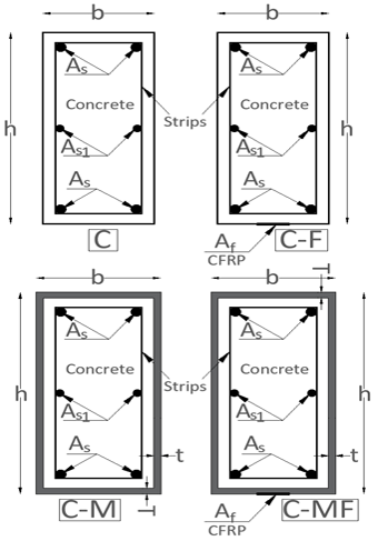
Figure 1. Types of studied beams sections.
| Symbols | Description | Unit |
|---|---|---|
| Pi | Internal axial force contribution of section component i | N |
| Mmax | Maximum elastic bending moment capacity | N.mm |
| AS | Area of tensile Steel reinforcement and Area of compressive reinforcing bars | mm² |
| AS1 | Area of Suspension bars | mm² |
| Af | Area of CFRP strip | mm² |
| a | Concrete cover thickness | mm |
| X | Distance of the Neutral axis from the top of the section | mm |
| h | Total section height | mm |
| b | Total section width | mm |
| T | Thickness of the horizontal parts of the metal tube | mm |
| t | Thickness of the vertical parts of the metal tube | mm |
| Ԑsc | Strain at extreme compression steel reinforcement | – |
| Ԑss | Strain at extreme tensile steel reinforcement | – |
| Ԑ1 | Strain in the upper horizontal part of the metal tube | – |
| Ԑ2 | Strain in compressed longitudinal reinforcing bars | – |
| Ԑ3 | Average Strain in compacted concrete | – |
| Ԑ4 | Average strain in the compressed vertical sections of the metal tube | – |
| Ԑ5 | Strain in Suspension bars | – |
| Ԑ6 | Average strain in the tensile vertical sections of the metal tube | – |
| Ԑ7 | Strain in tensile longitudinal reinforcing bars | – |
| Ԑ8 | Strain in the lower horizontal part of the metal tube | – |
| Ԑ9 | Strain in CFRP strips | – |
| ES | Modulus of elasticity of steel (ACI Committee 318, 2014) | MPa |
| EC | Modules of elasticity of concrete (ACI Committee 318, 2014) | MPa |
In order to ensure clarity and reproducibility of the analytical formulation, all symbols utilized in the governing equations (Equations 1–11) are defined in Table 10. The notation adheres to the established principles of reinforced concrete mechanics and is consistent with the assumptions and material models adopted in accordance with ACI Committee 318 (2014).
In this study, three distinct sizes of rectangular hollow steel sections were utilized, with each size allocated to one of the three experimental groups. The objective of this selection was to investigate the influence of cross-sectional dimensions on structural behavior under various loading conditions. The geometric properties of the tested sections are presented below, with the sections arranged from smallest to largest. As illustrated in Table 11, the dimensions and parameters exhibited in Figure 1 for all models examined in the research are enumerated.
| N | NAME | h (mm) | b (mm) | As (mm²) | As1 (mm²) | Strips (mm) | Af (mm²) | T (mm) | t (mm) |
|---|---|---|---|---|---|---|---|---|---|
| 1 | Small-C | 189.2 | 89.2 | 226.3 | - | Ø6/150mm | - | - | - |
| 2 | Small-CF | 189.2 | 89.2 | 226.3 | - | Ø6/150mm | 70 | - | - |
| 3 | Small-CM | 200 | 100 | 226.3 | - | Ø6/150mm | - | 5.9 | 5.9 |
| 4 | Small-CMF | 200 | 100 | 226.3 | - | Ø6/150mm | 70 | 5.9 | 5.9 |
| 5 | Medium-C | 284 | 134 | 339.4 | - | Ø6/150mm | - | - | - |
| 6 | Medium-CF | 284 | 134 | 339.4 | - | Ø6/150mm | 140 | - | - |
| 7 | Medium-CM | 300 | 150 | 339.4 | - | Ø6/150mm | - | 8 | 8 |
| 8 | Medium-CMF | 300 | 150 | 339.4 | - | Ø6/150mm | 140 | 8 | 8 |
| 9 | Large-C | 375 | 175 | 462 | 308 | Ø8/150mm | - | - | - |
| 10 | Large-CF | 375 | 175 | 462 | 308 | Ø8/150mm | 420 | - | - |
| 11 | Large-CM | 400 | 200 | 462 | 308 | Ø8/150mm | - | 12.5 | 12.5 |
| 12 | Large-CMF | 400 | 200 | 462 | 308 | Ø8/150mm | 420 | 12.5 | 12.5 |
In one of the experimental assemblies, a rectangular metal section of type TUBO 200×100×5.9 mm was utilized, as illustrated in Figure 2. This section presents the fundamental geometric characteristics derived from numerical analysis, encompassing the primary dimensions, inertia properties, and resistance moments, as delineated in Table 12. As demonstrated in Table 12, the section exhibits elevated stiffness around the strong axis (I33), rendering it conducive to resisting moments and bending in the vertical direction. The symmetry of the flange and web thicknesses also indicates consistent performance under dual loads.
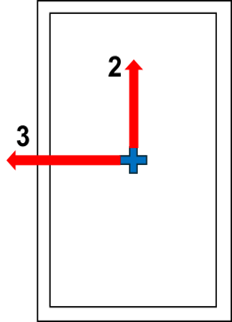
Figure 2. Type TUBO 200×100×5.9
| Dimensions | Value | Unit |
|---|---|---|
| Total depth | 200 | mm |
| Total width | 100 | mm |
| Flange thickness | 5.9 | mm |
| Web thickness | 5.9 | mm |
| Dimensions | Value | Unit |
|---|---|---|
| Area (A) | 34 | cm² |
| Moment about the strong axis (I33) | 1767 | cm⁴ |
| Inertia moment about the weak axis (I22) | 590.6 | cm⁴ |
| Polar moment (J) | 1366 | cm⁴ |
| Inertia radius about the strong axis (R33) | 72.1 | mm |
| Inertia radius about the weak axis (R22) | 41.7 | mm |
| Resisting moment about the strong axis (S33) | 176.7 | cm³ |
| Resisting moment about the weak axis (S22) | 118.1 | cm³ |
In one of the experimental arrangements, a rectangular metal section of the type TUBO 300×150×8 mm (Figure 3) was utilized. This shape indicates the basic geometric characteristics as obtained from the numerical analysis, including the main dimensions, inertia properties, and moments of resistance (Table 13). As demonstrated in Table 13, the section exhibits substantial stiffness about the strong axis (I33), rendering it suitable for resisting moments and bending in the vertical direction. The symmetry observed in the Flange and web thicknesses suggests equivalent performance under dual loading conditions.
Figure 3. Type TUBO 300×150×8
| Dimensions | Value | Unit |
|---|---|---|
| Total depth | 300 | mm |
| Total width | 150 | mm |
| Flange thickness | 8 | mm |
| Web thickness | 8 | mm |
| Dimensions | Value | Unit |
|---|---|---|
| Area (A) | 69.4 | cm² |
| Moment about the strong axis (I33) | 8171 | cm⁴ |
| Inertia moment about the weak axis (I22) | 2743 | cm⁴ |
| Polar moment (J) | 6338 | cm⁴ |
| Inertia radius about the strong axis (R33) | 108.5 | mm |
| Inertia radius about the weak axis (R22) | 62.9 | mm |
| Resisting moment about the strong axis (S33) | 544.7 | cm³ |
| Resisting moment about the weak axis (S22) | 365.7 | cm³ |
In one of the experimental assemblies, a rectangular metal section of type TUBO 400×200×12.5 mm was utilized, as illustrated in Figure 4. This section presents the fundamental geometric characteristics derived from numerical analysis, encompassing the primary dimensions, inertia properties, and resistance moments, as delineated in Table 14. The aforementioned values indicate that the section exhibits elevated stiffness around the primary axis (I33), rendering it conducive to resisting moments and bending in the vertical direction. The symmetry of the flange and web thicknesses also indicates consistent performance under dual loads.
Figure 4. Type TUBO 400×200×12.5
| Dimensions | Value | Unit |
|---|---|---|
| Total depth | 400 | mm |
| Total width | 200 | mm |
| Flange thickness | 12.5 | mm |
| Web thickness | 12.5 | mm |
| Dimensions | Value | Unit |
|---|---|---|
| Area (A) | 143.8 | cm² |
| Moment about the strong axis (I33) | 29760 | cm⁴ |
| Inertia moment about the weak axis (I22) | 9919 | cm⁴ |
| Polar moment (J) | 22950 | cm⁴ |
| Inertia radius about the strong axis (R33) | 143.9 | mm |
| Inertia radius about the weak axis (R22) | 83.1 | mm |
| Resisting moment about the strong axis (S33) | 1488 | cm³ |
| Resisting moment about the weak axis (S22) | 991.9 | cm³ |
The metal tube can be utilized during the construction phase in one of two ways. The reinforcing beam can be prepared as a precast concrete unit, or holes can be drilled into the metal tube and concrete can be poured through them after installation on site, as illustrated in Figure 5.
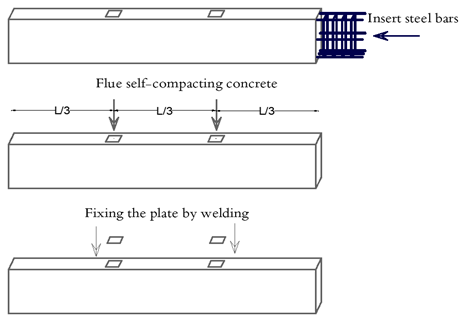
Figure 5. The Method of Cast the Strengthened Beam.
A simplified closed-form expression has been developed to estimate the moment capacity of the composite beam section. The solution is predicated on the equilibrium of forces across the section, as illustrated in Figure 6.
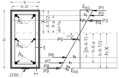
Figure 6. Strain and Forces Distribution for a Fully Elastic Cross-Section.
The equation after reform becomes as follows:
\[\frac{\varepsilon_{ss} \cdot E_s}{h - X} \cdot \left[ (X - a) \cdot A_s + \left( X - \frac{T}{2} \right) \cdot b \cdot T + \frac{4}{3} (X - T)^2 \cdot t + \frac{2}{3} (X - T)^2 \cdot (b - 2t) \cdot \frac{E_c}{E_s} \right]\] \[= \frac{\varepsilon_{ss} \cdot E_s}{h - X} \cdot \left[ \left( \frac{h}{2} - X \right) \cdot A_{s1} + \frac{4}{3} (h - X - T)^2 \cdot t + (h - X - a) \cdot A_s + \left( h - X - \frac{T}{2} \right) \cdot b \cdot T \right] + (h - X) \cdot A_f \cdot E_f\]It can be written as a quadratic equation as follows:
\[X^2 \left[ \frac{2}{3} (b - 2t) \frac{E_c}{E_s} \right] + X \left[ 2A_s + 2bT - \frac{8}{3}Tt + A_{s1} - \frac{4}{3}T(b - 2t)\frac{E_c}{E_s} + \frac{8}{3}t(h - T) + \frac{A_fE_f}{E_s} \right]\] \[+ \left[ -aA_s - \frac{4}{3}T^2t + \frac{2}{3}T^2(b - 2t)\frac{E_c}{E_s} - \frac{h}{2}A_{s1} - \frac{4}{3}t(h - T)^2 - (h - a)A_s - hbT + \frac{T^2}{2}b - \frac{hA_fE_f}{E_s} \right] = 0 \tag{10}\]The maximum elastic moment capacity is calculated with Equation. 11
\[M_{max} = P_1 \cdot \left( X - \frac{T}{2} \right) + P_2 \cdot (X - a) + P_3 \cdot \frac{2}{3}(X - T) + P_4 \cdot \frac{2}{3}(X - T) + P_5 \cdot \left( \frac{h}{2} - X \right)\] \[+ P_6 \cdot \frac{2}{3}(h - X - T) + P_7 \cdot (h - X - a) + P_8 \cdot (h - X - T/2) + P_9 \cdot (h - X) \tag{11}\]Subsequent to the calculation of the sections utilizing the aforementioned equations, and under the supposition that the neutral line is situated above the center of the beam section, simplified analytical relationships were formulated. These relationships were derived from the assumption of a neutral axis positioned above the center of the section, with the objective of elucidating the contribution of each component of the section to the moment resistance. Due to the intricacy of the neutral axis movement in asymmetrical composite sections, a numerical analysis was conducted using finite element software. This approach circumvents the limitations of traditional methods and automatically handles changes in the neutral axis location. In this context, the utilization of analytical modeling is confined to its role as a preliminary instrument for comprehension. It does not serve as a surrogate for advanced numerical analysis.
The ensuing results were obtained: the arithmetic equations are valid in the case of a symmetrical section concerning a horizontal axis passing through its center, made of concrete covered with a metal box; in this case, the flexible line is above the center of the beam. However, subsequent to the incorporation of carbon fiber strips, the accuracy of these measurements is compromised, as the neutral line may be situated beneath the beam’s center. Consequently, it can be posited that the primary function of these relationships is to facilitate initial comprehension, rather than to serve as a definitive design instrument.
The model for all sections was developed using the Section Designer program, as outlined in ACI Committee 318 (2014), and the interaction and moment diagrams for each section were generated accordingly. As illustrated in Figure 6, the design of the section (Large-CMF) is depicted, while provides a visual representation of the interaction diagram for the aforementioned section. The subsequent sections were modeled in an identical manner.
Analytical Study
The section designer program was utilized in the construction of all the models examined subsequent to the delineation of all materials by their parameters, as specified in Table 9. As illustrated in Figure 7, the model in question is designated as Large-CMF. The program provides an interaction diagram for all the modeled specimens, as illustrated in Figures 9–20, for the same model (Large-CMF). Consequently, the moment diagrams for all specimens under consideration were obtained through modeling, as illustrated in Table 15 for the model designated as “Large-CMF.”
Table 15 presents the raw numerical values generated by the program. These values have been converted into graphs in the Results and Discussion section to illustrate the stages of elastic and ductile behavior (Jones et al., 2022).
In this analytical study, we assumed complete and sufficient cohesion between the polymer-reinforced carbon fiber (CFRP) strips and both the concrete and the metal box. This assumption is consistent in practice with the reinforcement technique known as MF-EBR (Mechanically Fixed and Externally Bonded Reinforcement), where epoxy bonding is combined along the length of the strip with mechanical fastening at its ends. The loss of adhesion is one of the critical failure modes that will be the focus of detailed study in subsequent experimental research. This research will include fastening details, adhesion behavior, and associated failure modes.
The present study focuses on evaluating the maximum capacity of the structural section from an analytical perspective, rather than on design according to the safety factors adopted in the codes. It should be noted that a comparison with the requirements of the design codes (ACI 318, Eurocode 2, etc.) and safety factors will be carried out in subsequent studies dedicated to design applications.
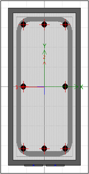
Figure 7. Modeling of Large-CMF Section.
As illustrated in Figure 8, this model provides a general representation of the axes and moments acting on a three-dimensional concrete member. This representation is employed for the purpose of analysis, while the section is designed and reinforced in accordance with the requirements of ACI Committee 318 (2014) for bending, torsion, and interaction between loads.
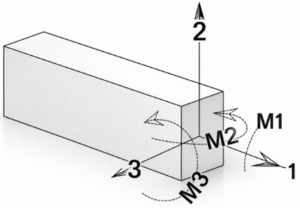
Figure 8. Illustrative Model of the Three Axes of Moment in a Solid Body
Axes 1, 2, and 3 represent the local coordinate axes of origin. The x-axis, delineated horizontally to the right, is employed for the study of moment or rotation around this direction. The vertical axis, designated as “Axis 2,” is employed as the y-axis and symbolizes the vertical direction of the origin. The axis 3, delineated diagonally towards the depth, functions as the z-axis and delineates the third dimension that emerges from the plane of the structure.
The representation of moments is accomplished by the use of curved dotted arrows, which indicate the direction of rotation in accordance with the right-hand rule. Moment M1 is defined as the moment of axis 1, causing the origin to rotate about the horizontal axis. This concept is frequently employed in the analysis of bending about the longitudinal axis. The M2 moment is defined as the moment of axis 2, which causes the body to rotate about the vertical axis. This moment is significant in the analysis of lateral bending. The M3 moment signifies the moment of axis 3, thereby inducing rotation of the body about the axis perpendicular to the front plane. The M3 moment is employed in the study of torsion.
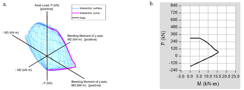
Figure 9. Interaction Diagrams of the Small-C Strengthened Section: a. Three-Dimensional Axial Load–Biaxial Bending Interaction Surface (P–M2–M3), Illustrating the Ultimate Capacity Envelope Under Combined Axial Load and Bending Moments; b. Corresponding Axial Load–Bending Moment (P–M) Interaction Curve Extracted from the Three-Dimensional Surface. Positive Axial Load Denotes Compression.
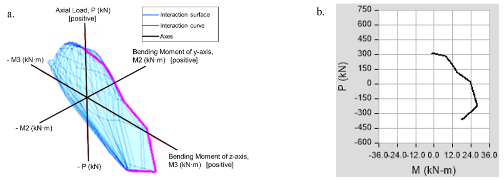
Figure 10. Interaction Diagrams of the Small-CF Strengthened Section: a. Three-Dimensional Axial Load–Biaxial Bending Interaction Surface (P–M2–M3), Illustrating the Ultimate Capacity Envelope Under Combined Axial Load and Bending Moments; b. Corresponding Axial Load–Bending Moment (P–M) Interaction Curve Extracted from the Three-Dimensional Surface. Positive Axial Load Denotes Compression.
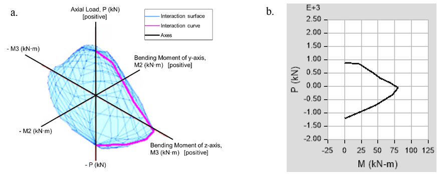
Figure 11. Interaction Diagrams of the Small-CM Strengthened Section: a. Three-Dimensional Axial Load–Biaxial Bending Interaction Surface (P–M2–M3), Illustrating the Ultimate Capacity Envelope Under Combined Axial Load and Bending Moments; b. Corresponding Axial Load–Bending Moment (P–M) Interaction Curve Extracted from the Three-Dimensional Surface. Positive Axial Load Denotes Compression.
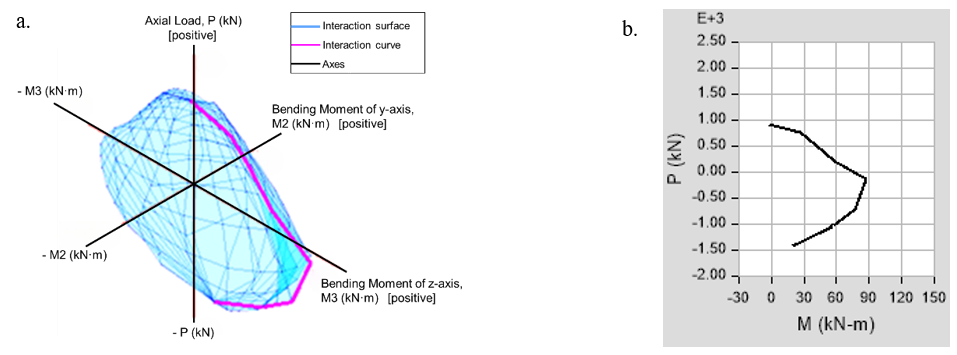
Figure 12. Interaction Diagrams of the Small-CMF Strengthened Section: a. Three-Dimensional Axial Load–Biaxial Bending Interaction Surface (P–M2–M3), Illustrating the Ultimate Capacity Envelope Under Combined Axial Load and Bending Moments; b. Corresponding Axial Load–Bending Moment (P–M) Interaction Curve Extracted from the Three-Dimensional Surface. Positive Axial Load Denotes Compression.
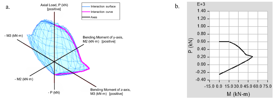
Figure 13. Interaction Diagrams of the Medium-C Strengthened Section: a. Three-Dimensional Axial Load–Biaxial Bending Interaction Surface (P–M2–M3), Illustrating the Ultimate Capacity Envelope Under Combined Axial Load and Bending Moments; b. Corresponding Axial Load–Bending Moment (P–M) Interaction Curve Extracted from the Three-Dimensional Surface. Positive Axial Load Denotes Compression.
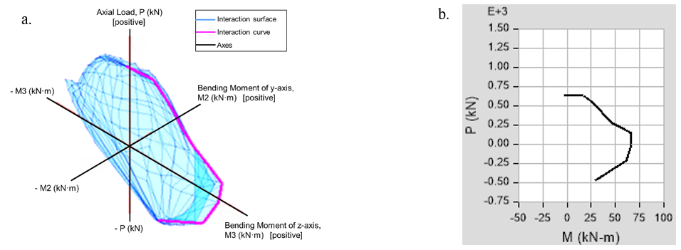
Figure 14. Interaction Diagrams of the Medium-CF Strengthened Section: a. Three-Dimensional Axial Load–Biaxial Bending Interaction Surface (P–M2–M3), Illustrating the Ultimate Capacity Envelope Under Combined Axial Load and Bending Moments; b. Corresponding Axial Load–Bending Moment (P–M) Interaction Curve Extracted from the Three-Dimensional Surface. Positive Axial Load Denotes Compression.
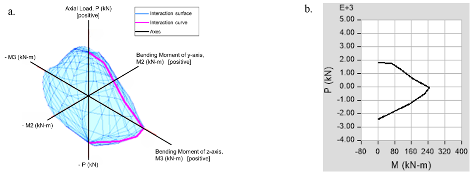
Figure 15. Interaction Diagrams of the Medium-CM Strengthened Section: a. Three-Dimensional Axial Load–Biaxial Bending Interaction Surface (P–M2–M3), Illustrating the Ultimate Capacity Envelope Under Combined Axial Load and Bending Moments; b. Corresponding Axial Load–Bending Moment (P–M) Interaction Curve Extracted from the Three-Dimensional Surface. Positive Axial Load Denotes Compression.
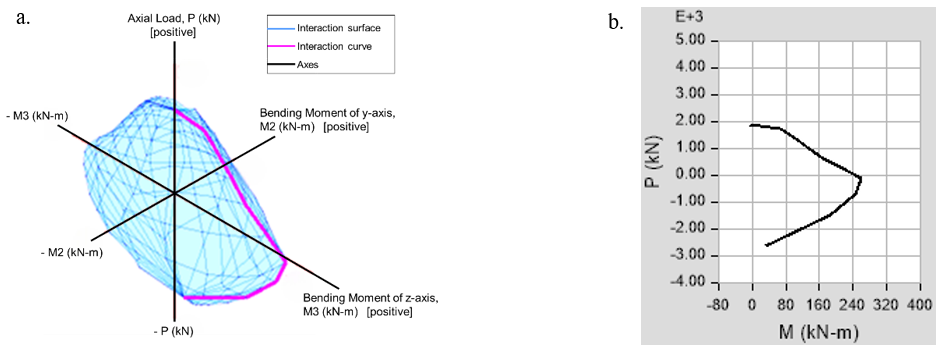
Figure 16. Interaction Diagrams of the Medium-CMF Strengthened Section: a. Three-Dimensional Axial Load–Biaxial Bending Interaction Surface (P–M2–M3), Illustrating the Ultimate Capacity Envelope Under Combined Axial Load and Bending Moments; b. Corresponding Axial Load–Bending Moment (P–M) Interaction Curve Extracted from the Three-Dimensional Surface. Positive Axial Load Denotes Compression.
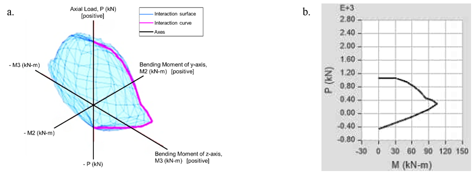
Figure 17. Interaction Diagrams of the Large-C Strengthened Section: a. Three-Dimensional Axial Load–Biaxial Bending Interaction Surface (P–M2–M3), Illustrating the Ultimate Capacity Envelope Under Combined Axial Load and Bending Moments; b. Corresponding Axial Load–Bending Moment (P–M) Interaction Curve Extracted from the Three-Dimensional Surface. Positive Axial Load Denotes Compression.
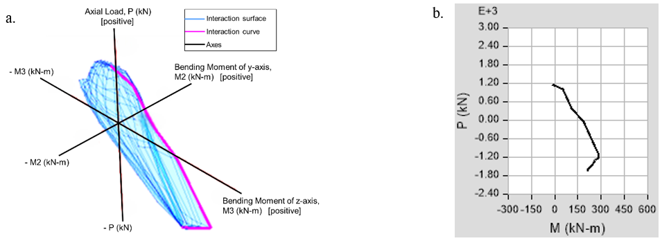
Figure 18. Interaction Diagrams of the Large-CF Strengthened Section: a. Three-Dimensional Axial Load–Biaxial Bending Interaction Surface (P–M2–M3), Illustrating the Ultimate Capacity Envelope Under Combined Axial Load and Bending Moments; b. Corresponding Axial Load–Bending Moment (P–M) Interaction Curve Extracted from the Three-Dimensional Surface. Positive Axial Load Denotes Compression.
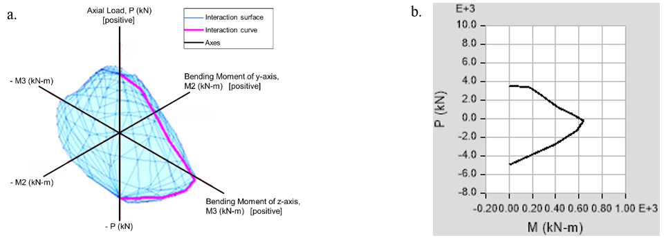
Figure 19. Interaction Diagrams of the Large-CM Strengthened Section: a. Three-Dimensional Axial Load–Biaxial Bending Interaction Surface (P–M2–M3), Illustrating the Ultimate Capacity Envelope Under Combined Axial Load and Bending Moments; b. Corresponding Axial Load–Bending Moment (P–M) Interaction Curve Extracted from the Three-Dimensional Surface. Positive Axial Load Denotes Compression.
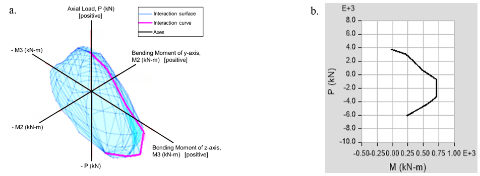
Figure 20. Interaction Diagrams of the Large-CMF Strengthened Section: a. Three-Dimensional Axial Load–Biaxial Bending Interaction Surface (P–M2–M3), Illustrating the Ultimate Capacity Envelope Under Combined Axial Load and Bending Moments; b. Corresponding Axial Load–Bending Moment (P–M) Interaction Curve Extracted from the Three-Dimensional Surface. Positive Axial Load Denotes Compression.
| Point | Moment (kN·m) | Curvature (rad/mm) |
|---|---|---|
| 1 | 0 | 0 |
| 2 | 661.5 | 9.82E-06 |
| 3 | 816 | 2.46E-05 |
| 4 | 835.6 | 4.42E-05 |
| 5 | 883.6 | 6.87E-05 |
| 6 | 964.2 | 9.82E-05 |
| 7 | 988.2 | 1.33E-04 |
| 8 | 1006.2 | 1.72E-04 |
| 9 | 1024.7 | 2.16E-04 |
| 10 | 1040.7 | 2.65E-04 |
| 11 | 1056.3 | 3.19E-04 |
| 12 | 1070.3 | 3.78E-04 |
| 13 | 1085.0 | 4.42E-04 |
| 14 | 1100.8 | 0.001 |
| 15 | 1052.1 | 0.001 |
| 16 | 1054.7 | 0.001 |
| 17 | 1054.5 | 0.001 |
Table 15 presents the raw numerical values that were generated by the program. Concurrently, these results have been thoroughly converted into graphical representations within the Results and Discussion section. These graphs serve to illustrate the stages of elastic and ductile behavior.
The research encompassed a study of the reinforcement of concrete bridges (concrete beams) across three distinct levels of reinforcement systems. The objective of this study was to evaluate the efficiency and effectiveness of each technique independently. The levels were as follows: At the fundamental level 1, the implementation of carbon fiber strips (CFRP) is employed as an external method of reinforcement. The second level of the project involves the completion of the concrete section with the application of steel tube jacketing. This addition is intended to enhance the section’s flexural behavior. Level 3 (most effective) involves the integration of the two preceding techniques, namely the combination of carbon fiber and steel jacketing, with the objective of enhancing the structural performance.
Due to the fundamental differences among published studies in terms of section geometry, strengthening configurations, material properties, modeling assumptions, and the level of analysis (structural section versus full beam behavior), a direct quantitative comparison within a unified table was deemed scientifically inappropriate and potentially misleading. Conversely, the present study employs a unified numerical–analytical framework, wherein all models are developed using consistent assumptions, material laws, and analysis procedures. This approach enables an accurate and reliable quantitative comparison of the relative effectiveness of the proposed strengthening techniques within the same research scope. Furthermore, comparisons with existing literature are discussed qualitatively to provide contextual support for the obtained results.
To facilitate a comparative analysis of the three reinforcement techniques, the results of the numerical analysis of the curves relating to the moment applied to the section and the resulting rotation were utilized.
Figures 9, 10, 11, and 12 illustrate the axial load–bending moment interaction behavior of the small section for C, CF, CM, and CFM, respectively. The three-dimensional interaction surface delineates the ultimate capacity envelope under combined axial load and biaxial bending. Concurrently, the extracted P–M curve underscores the variation of flexural capacity with axial force.
Figures 13, 14, 15, and 16 illustrate the axial load–bending moment interaction behavior of the medium section for C, CF, CM, and CFM, respectively. The three-dimensional interaction surface delineates the ultimate capacity envelope under combined axial load and biaxial bending. Concurrently, the extracted P–M curve underscores the variation of flexural capacity with axial force.
Figures 17, 18, 19, and 20 illustrate the axial load–bending moment interaction behavior of the large section for C, CF, CM, and CFM, respectively. The three-dimensional interaction surface delineates the ultimate capacity envelope under combined axial load and biaxial bending. Concurrently, the extracted P–M curve underscores the variation of flexural capacity with axial force.
The moment-curvature relationships were extracted directly in tabular form from the Section Designer program. This program relies on analyzing the section under the influence of pure bending to express the structural behavior of the section and its response to the applied moment. This is done without being linked to the support conditions or the method of applying loads at the full origin level. The objective of this analytical approach is to examine the local behavior of the section under consideration, independent of the nature of the load or support system.
The curves for each analytical group, consisting of four models (a reference model and three reinforced models), were then compiled into a single diagram to facilitate visual and analytical comparison between the behavior of the different models. The bending moment diagrams for the analyzed structures are presented in Figures 21, 22, and 23.
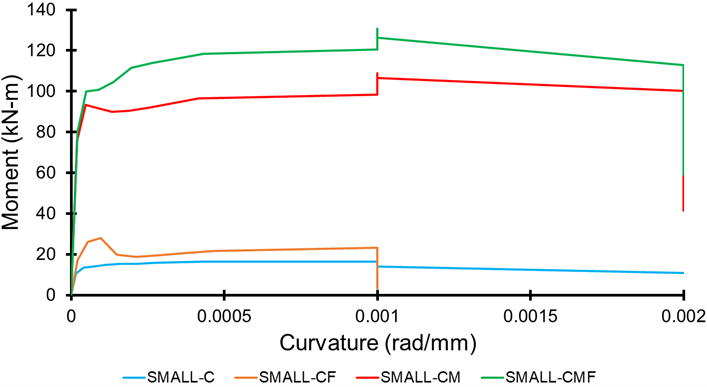
Figure 21. Moment Diagrams for Small (C-CF-CM-CMF) Sections.
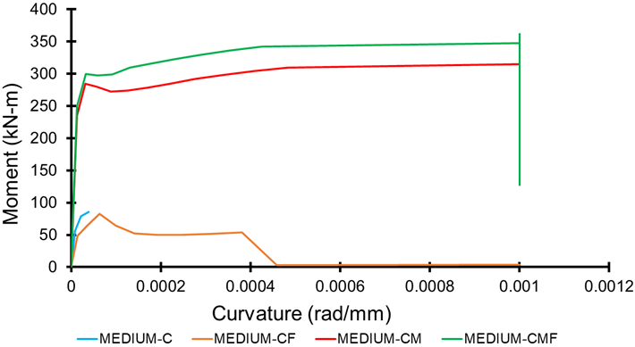
Figure 22. Moment Diagrams for Medium (C-CF-CM-CMF) Sections.
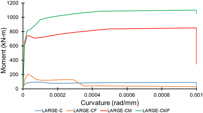
Figure 23. Moment Diagrams for Large (C-CF-CM-CMF) Sections.
The implementation of carbon fiber reinforcement technology resulted in a substantial relative augmentation in the flexural capacity of the sections, with the first group (small sections) demonstrating a 58.1% increase, the second group exhibiting a 72.7% increase, and the third group showing an impressive 117.2% increase compared to unreinforced concrete sections.
A comparison of the present study with previous research on concrete reinforcement with carbon fiber composites, such as the study by Xiao et al. (2025), which proposed a new reinforcement technique by combining two materials, is warranted. The resulting composite is referred to as a carbon fiber-coated steel plate (FESP). The enhancement in flexural capacity was recorded at 24.9%. This phenomenon can be attributed to the higher tensile strength of carbon fibers relative to the composite strip (FESB). Additionally, the ratio of the cross-sectional area of the reinforcement strip to that of the concrete section plays a significant role in these observations.
In comparison, research (Hawileh et al., 2022) that studied reinforcement using carbon fiber strips with a metal mesh reported a 58% increase in flexural capacity, which is lower than the improvement recorded in this study. A study was conducted to examine the effect of reinforcement patterns on the flexural performance of continuous reinforced concrete beams using fiber-reinforced polymer reinforcements. The study concluded that reinforcement with carbon fiber strips results in an increase in flexural capacity ranging from 8% to 50%.
A thorough examination of the three prior Figures 6, 7, and 8 reveals that the incorporation of carbon fiber-reinforced polymer strips within the concrete segment of the beam (C) did not yield a substantial enhancement in its flexural capacity. This phenomenon can be attributed to the integration of CFRP strips, which enhanced the tensile strength of the lower section while maintaining the compressive strength of the upper section.
The efficacy of the reinforcement technique employing metal pipes wrapped around concrete sections was found to exceed that of the reinforcement technique utilizing carbon fiber strips. This outcome resulted in a substantial relative increase in the flexural capacity of the sections, reaching 514% for the first group (small sections), 586% for the second group (medium sections), and 785% for the third group (large sections) in comparison to unreinforced concrete sections.
Preliminary studies suggest that the concept of enhancing concrete sections is predominantly proposed in the context of utilizing concrete jackets, as evidenced by research findings (Codina et al., 2025). In certain instances, novel methodologies have been put forth, as evidenced by research (Alrawi & Mahmood, 2022) entitled “Strengthening Reinforced Beams Subjected to Pure Torsion by Near Surface Mounted Rebars,” which examined the wrapping of concrete sections from three sides using metal mesh. This approach resulted in an enhancement of crack load by up to 129.2%.
In comparison, a substantial enhancement in the flexural capacity of the concrete section was observed when incorporating a metal tube surrounding the rectangular concrete section, i.e., when comparing case C and CM. This phenomenon is attributed to the steel tube’s capacity to resist tensile forces at the bottom of the section and compressive forces at the top. Additionally, the tube’s role in confining the concrete and increasing its compressive strength is considered. The aforementioned factors contributed to a substantial enhancement in the concrete section’s bending capacity.
A comparison of the CM and CMF models revealed that the incorporation of carbon fiber strips enhanced the section’s moment-resisting capacity. To accurately assess this improvement, a curve was drawn showing the comparison between the maximum elastic moments for all the models studied, as shown in Figure 24.
It is imperative to acknowledge that the substantial enhancement rates highlighted in the research findings signify an augmentation in the flexural capacity of the structural element subsequent to its transformation from a conventional concrete composition to a composite configuration (concrete-steel-CFRP), rather than an enhancement in the inherent properties of the concrete itself. The high efficiency of the section is accompanied by a significant increase in its area, which is resistant to tensile and compressive forces. The metal box plays a crucial role in confining the concrete and enhancing its compressive performance.
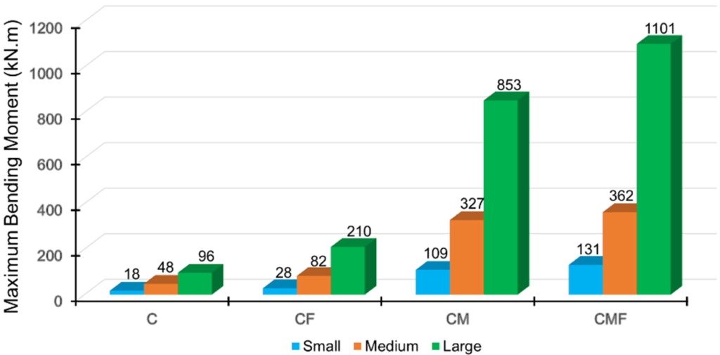
Figure 24. Maximum Elastic Moment Capacity for All Studied Sections.
The objective of this investigation is to critically study and analytically evaluate the structural performance of reinforced concrete beams strengthened using composite reinforcement systems composed of metal tubes and carbon fiber reinforced polymer (CFRP) sheets. The analytical and numerical models employed in this study indicate that the use of composite reinforcement systems can significantly enhance the mechanical response of reinforced concrete sections at the sectional level. This enhancement is particularly evident in terms of flexural resistance, stiffness enhancement, and delayed crack development within the elastic and pre-yielding range of behavior. Consequently, the proposed approaches to strengthening represent a significant analytical advancement in improving sectional performance within the scope of numerical analysis.
The numerical outcomes indicate that the implementation of CFRP strips as a strengthening method results in a substantial enhancement of flexural resistance, with an observed increase of approximately 82.7% compared to conventional reinforced concrete sections. The implementation of metal tubes for strengthening purposes yielded a substantial numerical improvement, amounting to approximately 628.2%. This enhancement can be ascribed to the dual contributions of the steel tubes. Firstly, they act as a barrier against compressive and tensile stresses. Secondly, they induce a confinement effect on the concrete core. The combined strengthening system, comprising metal tubes and CFRP strips, exhibited the most substantial analytical enhancement, with a total numerical improvement of approximately 791.3%, underscoring the efficacy of this integrated composite system in attaining an optimal balance between stiffness and strength at the sectional level.
A critical analytical comparison with reference studies reveals that the proposed system exhibits improved load transfer characteristics and a delayed development of critical stress states. These characteristics may contribute to enhanced structural reliability under extreme loading conditions at the sectional level and within the assumptions of the numerical model. The strengthening approach that utilizes metal tubes has demonstrated significant potential for implementation in both new construction and retrofitting scenarios. This approach does not necessitate substantial increases in section dimensions or structural weight when evaluated analytically.
The results further indicate the necessity of extending the present work to examine additional aspects, such as the influence of metal tube thickness and CFRP sheet thickness on overall behavior, as well as the response of strengthened sections under shear forces and composite moments. Additionally, the feasibility of prestressing CFRP strips prior to their installation within metal tubes should be investigated to enhance bonding efficiency and improve the numerical performance observed in this study. The investigation of additional composite reinforcement systems, integrating metallic meshes and CFRP materials, may also be undertaken to enhance the overall structural resilience.
In future research, it is further recommended that studies be conducted on energy absorption and ductility indicators, with a particular focus on the protection of composite sections from environmental factors such as moisture, corrosion, and heat. Additionally, when determining safety factors in practical applications, consideration should be given to the potential decrease in reinforcement efficiency over time.
This research makes a significant contribution to the field by enhancing the analytical understanding of composite-strengthened reinforced concrete sections. It presents a numerical, design-oriented framework that has the potential to support future experimental and applied studies. The outcomes of this work establish the foundation for developing more efficient, economical, and sustainable reinforcement solutions. These solutions are intended to extend the service life and improve the performance of reinforced concrete structures. However, it should be noted that these outcomes are subject to experimental validation and practical implementation considerations.
W.A: Methodology, Validation, Investigation, Resources, Writing of the original draft, Writing – review & editing, Visualization.
W.S: Conceptualization, Software, Formal analysis, Investigation, Data curation, Visualization.
The authors declare that they have no known competing financial interests or personal relationships that could have appeared to influence the work reported in this paper.
This research did not receive any specific grant from funding agencies in the public, commercial, or not-for-profit sectors.
No generative AI or AI-assisted technologies were used in the preparation of this manuscript.
The data that support the findings of this study are available from the corresponding author upon reasonable request.
The authors declare that there is no acknowledgement to be made.
This study did not involve human participants or animals; hence, no ethical approval was required.
Cite: Al-Dabbik, W., & Suliman, W. (2025). Enhancement of the Structural Performance of Reinforced Concrete Beam Sections Using CFRP and Metal Tubes: Design and Analysis. Steps For Civil, Constructions and Environmental Engineering, 3(4), 30-51. https://doi.org/10.61706/sccee12011222
![]() Copyright: © 2025 by the authors. Licensee Scientific Steps International Publishing Services, Dubai, UAE.
Copyright: © 2025 by the authors. Licensee Scientific Steps International Publishing Services, Dubai, UAE.
This article is an open access article distributed under the terms and conditions of the Creative Commons Attribution (CC BY) license (https://creativecommons.org/licenses/by/4.0/).


An independent academic publisher with an editorial team including many of the top researchers in the world. SSG publishes research, review, and case report articles in double-blind, peer-reviewed, open access scientific and academic journals.
Copyright © 2025 Scientific Steps International Publishing Services LLC (Dubai – United Arab Emirates)