
ISSN: 3005-8198 (online) | 3005-818X (print)
Volume 2, Issue 4 (October - December 2024) Pages 34-50
1 Department of Civil and Environmental Engineering, University of Balamand, Al Kurah, PO Box 100, Tripoli, Lebanon.
2 Faculty of Science and Engineering, University of Wolverhampton, Wolverhampton, UK.
The present study investigates the impact of steel fiber dosage and orientation on the structural performance of steel fiber-reinforced concrete (SFRC) beams through a combination of experimental testing and numerical simulation. RC beams with 0%, 0.25%, and 0.5% hooked-end steel fibers were evaluated under four-point bending. The findings indicated that the arrangement of horizontal fibers within the composite structure led to an enhancement in load-bearing capacity by up to 66% in comparison with the reference mixture. This observation was accompanied by the attainment of peak loads reaching 228.2 kN. In contrast, the alignment of vertical fibers within the composite exhibited an enhancement in stiffness, accompanied by a reduction in ductility. The random fiber distribution resulted in moderate performance outcomes. The finite element modeling (FEM) implemented in this study, utilizing the Abaqus software and the concrete damage plasticity (CDP) model, exhibited a high degree of concordance with the experimental outcomes, with prediction errors remaining within the 10% range. A comparison with ACI 318-19 revealed that conventional design models may overestimate shear strength, particularly for fiber-reinforced beams, by up to 87%. The findings emphasize the pivotal role of fiber alignment in enhancing the performance of RC beams and furnish valuable insights for formulating enhanced design strategies for seismic and high-load structural applications.
Keywords: Steel Fiber-Reinforced Concrete, Fiber Orientation and Dosage, Structural Performance of RC Beams, Finite Element Modelling, Shear and Flexural Strength.
Concrete beams represent a critical component within the domain of civil engineering applications, fulfilling the function of providing essential load-bearing capacity and facilitating load distribution. SFRC beams are frequently utilized to augment the tensile strength, ductility, and resistance to cracking under sustained and cyclic loads (Derseh et al., 2023; Ravichandran et al., 2022; Peng et al., 2023; Wang et al., 2024). The utilization of steel fibers in SFRC can be classified into five distinct categories, contingent upon their manufacturing process. These categories encompass milled, shaved, melt-extracted, cut sheet, and cold-drawn wire fibers. Cold-drawn wire fibers are the most frequently utilized due to their consistent quality and high tensile strength, while melt-extracted fibers are typically employed for specialized high-performance concrete applications. Cut sheet and shaved fibers contribute to enhanced toughness and crack resistance, whereas milled fibers are utilized less frequently in specific contexts (ASTM A820/A820M, 2016; Choi et al., 2020; Garber, 2014; Nhut et al., 2024; WALCOOM, 2024).
Despite the numerous benefits of SFRC, the resulting performance and mechanical properties remain highly sensitive to fiber dispersion and orientation. Optimal alignment has been demonstrated to improve flexural strength and load-bearing capacity (Li et al., 2023; González et al., 2023; Han et al., 2019). Poor fiber alignment has been demonstrated to undermine the intended reinforcement benefits (Hasan Tahsin Öztürk, 2024). Furthermore, exposure to chloride-rich or damp environments has been shown to accelerate corrosion and compromise structural integrity (Zheng et al., 2024). Research indicates that optimized fiber orientation can enhance durability, sustainability, and overall structural efficiency (Yang et al., 2024; Liu, et al., 2024; Michalik et al., 2023). Additionally, the morphology of steel fibers exerts a significant influence on the performance of SFRC (Hoseini et al., 2022; Kumar et al., 2024). For instance, crimped fibers enhance mechanical interlocking, hooked-end fibers improve bond strength and pull-out resistance, while twisted fibers offer superior crack-bridging properties. As demonstrated in the extant literature, other shapes, such as needle-like or flattened threads, have been shown to improve mechanical adherence and stress transfer efficiency (Fang et al., 2024; Guan, et al., 2024; Yadav et al., 2023; Zhang et al., 2023; Zia et al., 2023).
The optimization of the SFRC for specific structural applications necessitates the judicious selection of steel fibers with regard to both their type and shape (Kaushik et al., 2021; Shashikumara et al., 2023; Liu et al., 2017; Ramakrishnan, 2022). For instance, the utilization of recycled steel fibers derived from discarded tires has been shown to reduce greenhouse gas emissions by up to 67.62 kg CO2 per truck tire recycled (Zhang et al., 2023). Hybrid fiber blends, combining 30% industrial steel fibers and 70% recycled tire steel fibers, have been shown to increase compressive strength by 39% compared to conventional concrete while reducing material costs by 25% per cubic meter (Michalik et al., 2023; Zia et al., 2023). Additionally, SFRC requires 15–25% less maintenance than traditional concrete, providing long-term cost savings (Zhang et al., 2023).The mechanical superiority of SFRC is evident in increased flexural strength by 82.3% and up to 20% impact resistance, resulting in enhanced durability and structural integrity (Qin et al., 2024). The incorporation of rubber particles from recycled tires has been demonstrated to enhance toughness and impact resistance, thereby supporting sustainable building practices and circular economy principles (Zhang et al., 2024).
In regions characterized by high seismic activity, the incorporation of SFRC mixtures has been demonstrated to enhance the strength, durability, and crack resistance of structures. The incorporation of steel fibers, with a proportion of 1%, has been demonstrated to enhance peak load capacity by up to 38%, while concurrently reducing maintenance expenditures through the augmentation of environmental durability (Fares & Burak Bakir, 2024; Li, et al., 2024; Solahuddin Bin Azuwa & Bin, 2024). The enhanced fiber content and augmented fiber lengths have been demonstrated to improve fracture toughness and mechanical properties (Saatci et al., 2024; Wu et al., 2022). It is noteworthy that the orientation of steel fibers has been demonstrated to exert a pivotal influence on the performance of SFRC, with optimal alignments ranging from 0° to 30° exhibiting a marked enhancement in tensile, flexural, and fracture resistance. Radial fiber orientations have also been demonstrated to enhance shear resistance and post-peak performance (Huang et al., 2021; Mu et al., 2023; Qin et al., 2023; Zhang, Wang, et al., 2023). The employment of advanced techniques, including Computer Axial Tomography and the regulation of water-cement dynamics, has been demonstrated to further augment bond strength and durability (Lee & Kim, 2010; Lorente et al., 2022).
The utilization of numerical analysis tools is imperative in comprehending the behavior of SFRC beams. Various methodologies, including Finite Element Analysis (FEA), Discrete Element Method (DEM), Cohesive Zone Modeling (CZM), Extended Finite Element Method (XFEM), and Multiscale Modeling, offer insights into the intricate behavior of structural components. FEA is frequently employed for the purpose of stress-strain prediction. Conversely, DEM emphasizes the examination of fiber-matrix interactions. Additionally, CZM and XFEM are specialized methods that address crack propagation and fracture modeling (Zhang, Zhang, et al., 2024). Abaqus is a widely used computational tool for simulating these behaviors (Li, Wang, et al., 2024; Wang & Xu, 2024; Wei et al., 2024).
The objective of this study is to examine the impact of steel fiber dosage and orientation on the structural performance of normal strength SFRC beams. The objective of the research is to identify optimal beam configurations through a comparative analysis of numerical modeling and experimental testing. The analysis encompasses parameters such as shear strength, ductility, peak load capacity, displacement, and failure modes. A critical objective is the validation of finite element models using Abaqus, with a particular focus on load-deflection behavior, crack propagation, and damage patterns. Furthermore, the study makes a comparison between the experimental shear strength and the design shear strength values calculated using ACI 318-19 standards. This is done in order to assess the accuracy in predicting shear capacity and to support the refinement of SFRC design methodologies.
This study is founded on a prior investigation by Ghali et al. (2023), which examined the structural performance of reinforced concrete (RC) beams incorporating various fiber types and dosages. A control mix without fibers (0%) and two SFRC mixtures containing 0.25% and 0.5% steel fibers are tested in four-point bending. For each mixture, a beam with dimensions of 1200 mm in length, 150 mm in width, and 250 mm in height were cast. The effective depth and concrete cover were measured to be 225 and 25 mm, respectively (Figure 1). The beams were reinforced with two 20-millimeter longitudinal steel bars in the tension zone, 8-millimeter stirrups for shear reinforcement, and 8-millimeter longitudinal bars in the compression zone.
The concrete mix was developed for residential and precast applications, incorporating materials that meet relevant ASTM standards. The Portland cement utilized in this study conformed to ASTM C150 Type I specifications, while the limestone coarse and fine aggregates met ASTM C33 specifications. Additionally, the mixture contained natural siliceous sand. The specific gravities of the limestone aggregates and sand were 2.72 and 2.70, respectively, with corresponding water absorption rates of 0.55% and 0.6%, respectively. The mixture design included a cement content of 400 kg/m³ and a water-to-cement (w/c) ratio of 0.5, with the objective of achieving a 28-day compressive strength of 40 MPa, with a standard deviation of ±2.5 MPa. Aggregate proportions were optimized for gradation and packing density, with sand, fine aggregate, and coarse aggregate dosed at 702, 611, and 407 kg/m³, respectively. A high-range water-reducing admixture (HRWR), which complies with ASTM C494 Types A and F, was incorporated at 0.25% of the cement mass. This admixture was used to achieve a slump of 200 ± 20 mm, in accordance with ASTM C143.
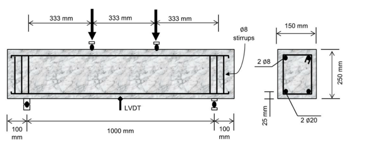
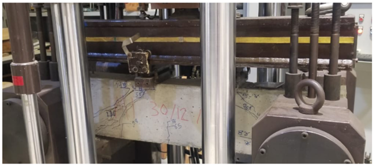
Figure 1. Beam Dimensions, Reinforcement Details, and Test Setup Under Two-Point Loading (Ghali et al., 2023).
Hooked-end steel fibers, with a length of 30 millimeters and a diameter of 1 millimeter, were utilized. These fibers possess an aspect ratio (lf/df) of 30, with tensile strengths ranging from 1100 to 1600 megapascals. These fibers were incorporated into the specimen at 0.25% and 0.5% volume fractions. To ensure uniform dispersion, the steel fibers were homogenized with aggregates and half of the mixing water for one minute prior to the addition of the remaining materials. A series of modifications were implemented in collaboration with HRWR, with the objective of ensuring the maintenance of the target slump.
The concrete materials were cast in plywood molds and subsequently compacted using a 100-Hz laboratory poker vibrator. Subsequent to a 24-hour demolding process, the specimens were subjected to a curing procedure in a lime-saturated water environment. This was conducted under controlled conditions, with temperature maintained at 22 ± 3°C and relative humidity levels set at 55 ± 10%. The specimens were then placed into a testing apparatus and subjected to a 28-day testing period. The beams were subjected to a series of tests that emulated real-world loading conditions. Utilizing a Universal Testing Machine with a maximum load capacity of 1000 kilonewtons, the beams were exposed to symmetrical two-point loading, which is a standard method in structural engineering. This approach allowed for the evaluation of their shear behavior under realistic loading conditions (Ghali et al., 2023). The load was applied at a controlled rate of 5 kN/min, and the shear span-to-effective depth ratio was set at 1.48. The measurement of deflections was conducted by employing linear variable differential transducers (LVDTs), strategically positioned at the midpoint of the span. The crack patterns and fracture openings were meticulously documented with the aid of a hand-held microscope as the load was reduced to approximately 50% of its peak value.
In order to investigate the influence of steel fiber orientation on the mechanical properties of concrete, two additional sets of mixes were prepared for each fiber dosage (0.25% and 0.5%). Cylindrical specimens with a diameter of 150 millimeters and a height of 300 millimeters were cast and subsequently tested to determine their compressive strength, tensile strength, and modulus of elasticity.
The specimens were cast in 15 successive layers, with each layer having a thickness of approximately 2 centimeters. For each layer, the steel fibers were manually positioned either vertically, as shown in Figure 2a, or horizontally, as shown in Figure 2b. While the horizontal alignment was relatively straightforward to manipulate, achieving optimal vertical alignment proved to be a more arduous task. Consequently, despite meticulous placement, some fibers exhibited slight inclinations and were not perfectly vertical. A particular emphasis was placed on the casting process to ensure minimal disruption to the fibers and to maintain their intended orientation throughout the specimen.
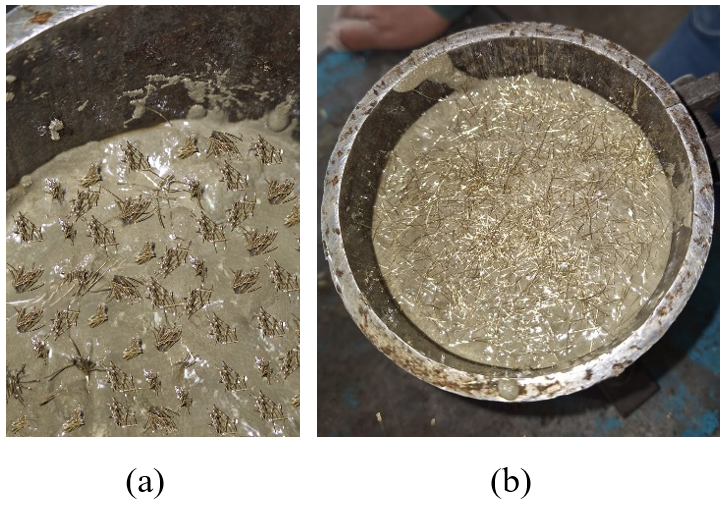
Figure 2. Preparation of Concrete Cylindrical Specimens With: (a) Verticals Steel Fibers (b) Horizontal Steel Fibers
In this study, the finite element method (FEM) software Abaqus was employed to simulate the structural behavior of SFRC beams under varying fiber orientations and dosages. Abaqus was selected due to its advanced capabilities in modeling nonlinear material behavior, including cracking, crushing, and plastic deformation of concrete. The developed finite element model (FEM) aimed to replicate the experimental conditions accurately, ensuring consistency between numerical and physical tests while enabling an in-depth assessment of fiber orientation effects on beam behavior. Given that Abaqus does not directly simulate discrete steel fibers, the material properties of structural reinforcement concrete (SFRC) were calibrated based on experimental findings. The impact of varying fiber orientations (random, vertical, and horizontal) manifested in alterations to critical parameters, including tensile strength, stiffness, and damage characteristics. This methodological approach enabled the model to accurately capture the influence of fiber orientation on structural response.
To characterize the concrete’s response under various loading conditions, the CDP model was implemented. This model is notable for its ability to account for crucial nonlinear phenomena, including compressive crushing, tensile cracking, and stiffness degradation under cyclic loading. The CDP model has been demonstrated to be particularly effective in capturing the inelastic behavior of concrete. The model incorporates both tensile and compressive damage mechanisms to simulate progressive failure in a realistic manner. The key input parameters, including density, elasticity modulus, and stress-strain curves for both tension and compression, will be determined through experimental means. These parameters will be discussed in the results section. An exhaustive list of additional parameters is provided in Table 1.
Table 1. CDP Parameters Adopted in Modeling

The reinforcing steel was modeled as an elastic-plastic material with strain-hardening behavior. The material was assigned a density of 7850 kg/m³, a Young’s modulus of 200 GPa, and a Poisson’s ratio of 0.3. The interaction between the steel reinforcement and the concrete matrix was modeled using an embedded constraint approach in Abaqus, ensuring accurate representation of the bond behavior.
A displacement-controlled loading methodology was adopted to ensure a realistic simulation of the progressive loading process, mirroring the experimental conditions. The maximum displacement values recorded during testing were utilized as reference points to drive the numerical analysis. A dynamic, explicit analysis step was implemented to capture the highly nonlinear behavior of SFRC beams, including large deformations and intricate contact interactions. The displacement was applied incrementally using an amplitude function to closely replicate the experimental loading conditions.
The precision of numerical outcomes is contingent on the employed meshing strategy. A structured mesh with a 25 mm element size was employed to discretize the concrete beam, striking a balance between computational efficiency and result accuracy (Figure 3). In order to enhance the resolution of stress gradients and deformation patterns, finer meshing was applied in critical regions, such as around the reinforcement and load application points. Contact interactions between the steel reinforcement and the concrete matrix were defined to account for bond-slip effects. To simulate normal behavior and prevent material penetration, a hard contact model was employed. A tangential friction coefficient of 0.2 was assigned to characterize sliding resistance at the steel-concrete interface.
The model validation process entailed a meticulous comparison of the numerical outcomes with the experimental data. This comparison was undertaken with a particular emphasis on pivotal parameters, including maximum load (Pmax), maximum displacement (δmax), and damage patterns. A robust correlation between numerical and experimental outcomes is essential for validating the precision and dependability of the model.
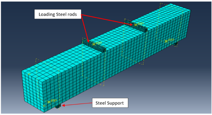
Figure 3. Modeling of the SFRC Beam in ABAQUS
As illustrated in Table 2, a comprehensive overview of the mechanical properties of concrete is provided, with specific attention devoted to the impact of varying fiber orientations and dosages. The 0.5% dosage with random fiber orientation exhibited the optimal performance in terms of modulus of elasticity (36.7 GPa) and compressive strength (51.9 MPa). This enhancement is attributed to the random dispersion of fibers, which effectively reinforces the concrete matrix in multiple directions, thereby inhibiting microcrack initiation and propagation. The fibers’ capacity to function as crack arrestors enhances their resistance to compressive loads, while ensuring a uniform stress distribution. Furthermore, the random orientation of the fibers within the cementitious matrix has been shown to reduce voids and enhance fiber interlocking, thereby increasing the stiffness of the material (i.e., higher modulus of elasticity). This, in turn, leads to an optimized structural integrity of the concrete.
In the tensile strength assessment, the horizontal fiber orientation at the 0.5% dosage demonstrated superior performance, attaining a maximum value of 3.98 MPa. This finding indicates that fibers aligned parallel to the applied tensile load exhibit enhanced crack-bridging capacity and tensile stress distribution. The 0.5% dosage exhibited a substantial enhancement in tensile strength when compared to the 0.25% dosage with horizontal fibers (3.72 MPa), suggesting that an augmented fiber content enhances load-carrying capacity and crack resistance. Across all dosages, horizontal fibers demonstrated a consistent increase in tensile strength relative to vertical fibers, which exhibited lower values of 3.17 MPa (0.5%) and 3.09 MPa (0.25%). This discrepancy can be attributed to the diminished capacity of fibers oriented vertically to resist tensile forces, a consequence of their misalignment with the predominant stress direction. In summary, the incorporation of steel fibers, with an initial dosage of 0.25%, was found to be a beneficial addition to the concrete mixture. A dosage of 0.5% was determined to be optimal, with horizontal fiber orientation enhancing tensile strength and random orientation enhancing compressive properties. A 0.5% dosage with horizontal fiber placement has been determined to be the most effective configuration for maximizing both compressive and tensile performance, ensuring superior mechanical strength and reinforcement efficiency.
Table 2. Mechanical Properties of Different Mixes
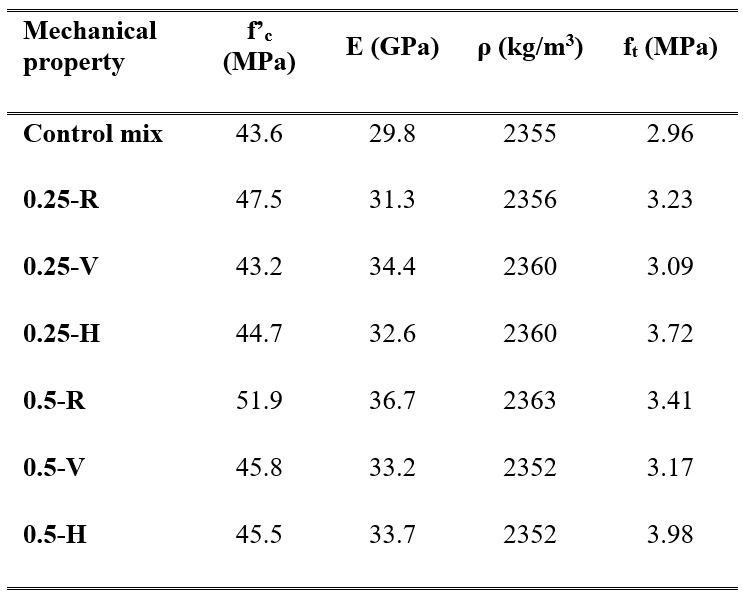
“R” is for random orientation of fibers, “V” is for vertical orientation of fibers, and “H” is for horizontal orientation of fibers.
The finite element model was validated against experimental results by comparing key structural parameters, including Pmax, δmax, and failure damage patterns across different steel fiber dosages (0.25% and 0.5%) and orientations (random, vertical, and horizontal). To ensure the accuracy of the results, the finite element method (FEM) outputs were maintained within a 10% allowable margin of error relative to the experimental data. In instances where deviations exceeded this threshold, the model underwent iterative refinement to enhance the alignment. It is evident that the FEM employed a meticulous calibration process, thereby effectively replicating the load-bearing capacity, deformation behavior, and fracture patterns that were observed in experimental tests.
The validation process has been undertaken to ascertain the reliability of the finite element method (FEM) in structural analysis, encompassing a range of fiber configurations. The primary objective is to verify the accuracy of the FEM in simulating the mechanical behavior of structural reinforced concrete (SFRC) beams. A comparison was made between the numerical model findings and the experimental results obtained by Ghali et al. (2023) for the control mix, 0.25-R, and 0.5-R. This comparison demonstrated a strong correlation. The failure patterns exhibited by the FEM model closely resembled the observed failure patterns in the experimental setup, as depicted in Figure 4.

Figure 4. Comparison of Numerical FEM Damage Predictions with Experimental Results for The Control Mix Beam, 0.25-R Beam, and 0.5-R Beam
The collapse of the structure was attributed to the propagation of a brittle oblique crack, extending at an angle ranging from 35 to 45 degrees from the support to the load application points. As illustrated by Figures 5-7, there is a high degree of consistency between the predictions made by the finite element method (FEM) and the experimental outcomes reported by Ghali et al. (2023). This consistency serves to reinforce the model’s ability to accurately predict the structural response of shear reinforced concrete (SFRC) beams.
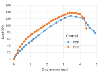
Figure 5. Load-Displacement Curves of The Control Beam – Comparison of FEM Predictions with Experimental Results
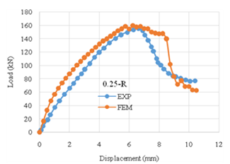
Figure 6. Load-Displacement Curves of 0.25-R Beam – Comparison of FEM Predictions with Experimental Results

Figure 7. Load-Displacement Curves of 0.5-R Beam – Comparison of FEM Predictions with Experimental Results
The investigation reveals that increasing the steel fiber dosage enhances the load-carrying capacity (Pmax) of SFRC beams; however, it can also lead to reduced displacement (𝛿max), particularly in vertically aligned fibers. At a 0.25% fiber content, the horizontal mix achieves a peak load of 186.19 kN with a displacement of 17.48 mm, whereas the vertical mix reaches 160.17 kN with a significantly lower displacement of 10.50 mm (Figure 8). This finding suggests that the orientation of horizontal fibers within the material effectively enhances energy dissipation and stress distribution, thereby increasing both strength and ductility. At a 0.5% fiber dosage, the vertical mix exhibited a notable increase in strength, reaching 202.88 kN; however, displacement was reduced by 10 mm, suggesting a significant increase in stiffness. Conversely, the 0.5% horizontal mix attains the maximum peak load of 228.23 kN while preserving a displacement of 16.58 mm, thereby exhibiting a balanced compromise between strength and deformability (Figure 9).
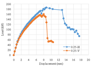
Figure 8. Load-Displacement Curves for SFRC Beams with 0.25% Fiber Content
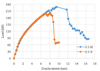
Figure 9. Load-Displacement Curves for SFRC Beams with 0.5% Fiber Content
A comparison of experimental and finite element method (FEM) results indicates that, while FEM tends to slightly overestimate Pmax, particularly at higher fiber dosages, it remains a reliable tool for predicting beam behavior. As illustrated in Figure 10, the load capacity varies according to the fiber configuration, demonstrating a consistent enhancement in strength with elevated fiber dosages, particularly for horizontally aligned fibers. However, as demonstrated in Figure 11, maximum displacement exhibits a decrease with increasing fiber content, with vertical fibers demonstrating the most substantial reduction in deformability. These findings suggest that while higher fiber dosages improve load resistance, they may also reduce ductility, particularly in vertical orientations. For applications requiring both strength and flexibility, it is recommended that a 0.5% horizontal fiber arrangement be employed. Conversely, if the primary objective is to maximize strength, a higher fiber dosage with vertical alignment is preferable, despite the trade-off in displacement. These insights can inform the optimization of SFRC beam designs to meet specific structural performance requirements.
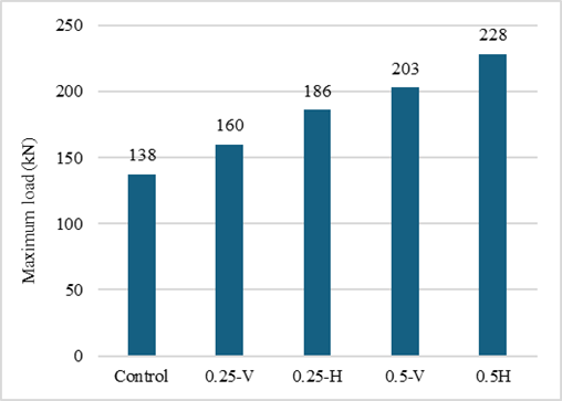
Figure 10. Comparison of Peak Load Capacities Across All Fiber Dosages and Orientations
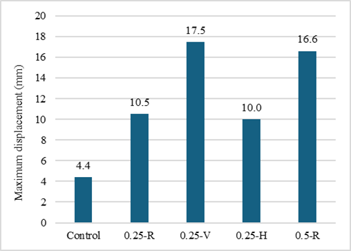
Figure 11. Displacement of SFRC Beams for Different Fiber Dosages and Orientations
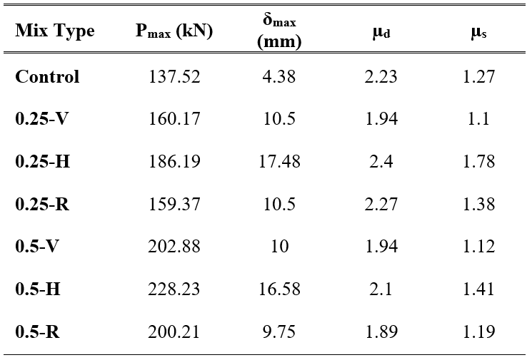
Two critical parameters must be considered when assessing the post-peak performance and energy dissipation capacity of SFRC: the displacement ductility ratio (μd) and the shear ductility ratio (μs). μd quantifies the material’s deformation capacity, while μs represents the ratio of energy absorbed during the post-peak phase (Aᵤ) to the energy absorbed up to the peak load (Ay). This ratio indicates the material’s capacity to dissipate energy prior to failure (Figure 12). These ratios are derived from the load-deflection curve by identifying the Pmax and defining the yield and ultimate points based on 80% of Pmax. The deflection at 80% of Pmax on the ascending branch is denoted as Δy, while Δᵤ represents the deflection at the same percentage on the descending branch. The energy absorption values, Ay (area under the curve until Pmax) and Aᵤ (area under the descending branch up to 75% of Pmax), are computed using the trapezoidal rule. The ductility ratios are subsequently determined through the application of the following equations:

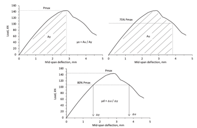
Figure 12. Displacement Ductility Ratio (μd) and Shear Ductility Ratio (μs) Relations
The findings presented in Table 3 demonstrate that an increase in fiber dosage leads to an enhancement in load capacity, while concurrently resulting in a reduction in displacement capacity. The lowest recorded Pmax was observed for the control mix, measuring 137.52 kN, while the highest was recorded for the 0.5% horizontal fiber mix, reaching 228.23 kN. However, the material flexibility, as indicated by the delta maximum (δmax), reaches its peak at 17.48 millimeters at a horizontal fiber dosage of 0.25 percent. It is observed to decrease with increasing fiber concentrations, reaching 9.75 millimeters at a 0.5 percent random fibers dosage. A comparable trend is observed in the μd, which attains a maximum of 2.4 for 0.25% horizontal fibers before exhibiting a decline with augmented fiber content. Conversely, the shear ductility ratio (μs) exhibits a maximum value for 0.25% horizontal fibers (1.78). However, as fiber dosage increases, the μs ratio experiences a decline. These findings suggest that while higher fiber content enhances load resistance, it compromises deformation capacity. Among the configurations that were tested, the 0.25% horizontal fiber mix demonstrated the optimal balance between strength and ductility, thus making it the most effective option for applications necessitating both resilience and structural integrity.
Table 3. Ductility Ratios of All Mixes.
The theoretical shear strength (Vaci) and the experimentally determined ultimate shear strength (Vu) for different SFRC mixes are compared in Table 4. The shear strength (Vu) was calculated using Pmax, which was obtained from experimental testing. The theoretical shear strength (Vaci) was determined following the ACI 318-19 guidelines, which account for the contributions of both reinforcement and concrete. This comparison offers insights into the accuracy of the ACI shear design model in predicting the shear performance of SFRC beams.
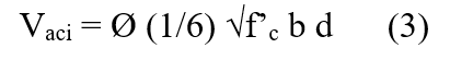
The findings suggest that the ACI 318-19 model has a tendency to overestimate shear strength, as evidenced by the predominance of Vu/Vaci ratios greater than 1. This finding indicates that the concrete contribution predicted by the ACI shear strength formula (Vaci) is often greater than the experimentally observed shear strength (Vu). Furthermore, the data demonstrates that the presence and orientation of steel fibers have a substantial impact on shear behavior, with the highest Vu/Vaci ratios observed in mixes with higher fiber dosages and horizontal fiber alignment. This underscores the significance of fiber orientation in augmenting shear resistance. In summary, the findings indicate that while ACI 318-19 establishes conservative shear design criteria, adjustments may be required when incorporating steel fibers to more accurately reflect their impact on shear performance.
Table 4. Shear Strength Vu and Vaci
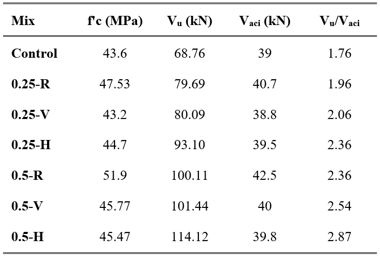
This study employed Abaqus to simulate damage patterns in concrete beams, comparing control and steel fiber-reinforced mixes (0.25% and 0.5% fiber dosages) with horizontal (H), vertical (V), and random (R) fiber orientations at critical load stages—0.25P, 0.75P, and Pmax. The analysis yielded insights into the influence of fiber orientation and dosage on structural response, stress redistribution, and damage mitigation. The objective of the present study was to enhance understanding of how steel fibers contribute to improving the ductility and resilience of concrete beams. To this end, failure mechanisms were examined under different configurations. Figures 13, 14, and 15 illustrate the damage patterns for the 0.25% steel fiber dosage, 0.5% steel fiber dosage, and control mix, respectively.
The control mix (Figure 15) exhibited shear-dominated brittle failure, characterized by diagonal cracks propagating from the support to the load application points. In the context of fiber-reinforced mixtures, the failure mechanisms exhibited variability in accordance with the dosage and orientation of the fibers. Although vertical fibers were less effective in resisting lateral stresses, they contributed to stress redistribution along the beam, leading to milder diagonal cracks. The horizontal fibers, especially in the 0.5% dosage (Figure 14), exhibited a substantial enhancement in failure resistance by bridging cracks along the shear plane. This effect led to a more dispersed crack pattern and an augmentation in ductility. The 0.25% fiber-reinforced beam (Figure 13) exhibited an intermediate response, characterized by reduced crack propagation compared to the control mix but lower energy dissipation than the 0.5% dosage. Balanced behavior was exhibited by the random fibers, characterized by the maintenance of diagonal failure characteristics and the facilitation of a certain degree of crack dispersion. These findings indicate that fiber orientation plays a crucial role in modifying the failure mode, with horizontal fibers offering the most substantial improvement in structural integrity.
Figure 13. Damage Pattern for Beams 0.25-H, 0.25-V, and 0.25-R.
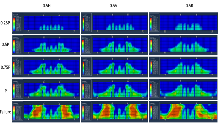
Figure 14. Damage Pattern for Beams 0.5-H, 0.5-V, and 0.5-R.
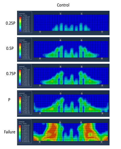
Figure 15. Damage Pattern for The Control Beam.
As illustrated in Table 5 and Figure 16, a comparison is made of the failure mechanisms and damage patterns of SFRC mixes with varying fiber dosages and orientations. The control mix demonstrated deficient load redistribution capacity, resulting in concentrated cracking, diminished ductility, and brittle failure, with a substantial damage percentage of 22.50%. Conversely, the presence of fibers in the mixture resulted in a more dispersed and less severe damage pattern, underscoring the role of fibers in enhancing structural resilience. Among all configurations, horizontal fibers demonstrated the most effective crack bridging and shear resistance, resulting in the lowest damage rates at both 0.25% (17.29%) and 0.5% (18.96%) dosages. While the addition of vertical fibers led to an increase in load capacity, it was observed that these fibers exhibited higher damage percentages, with values of 19.38% and 23.96%, respectively. This finding suggests that the vertical fibers may have contributed to less effective stress distribution and limited shear resistance. The fibers displayed intermediate performance, with damage rates of 22.71% at 0.25% and 23.13% at 0.5%, suggesting that their dispersed orientation is less efficient in mitigating stress concentration at critical locations.
The analysis further established an inverse relationship between damage extent and ductility, with horizontal fibers consistently demonstrating the highest performance. In comparison with the control mix, which demonstrated low ductility, the 0.25% horizontal fiber mix attained optimal ductility ratios (μd = 2.4, μs = 1.78), effectively absorbing energy and deforming under stress. In contrast, the use of vertical fibers, despite their higher strength, resulted in greater damage and lower ductility ratios (μd = 1.10, μs = 1.10) due to their restricted shear resistance. The performance of the random fibers was moderate, exhibiting balance in both vertical and horizontal configurations. In general, horizontal fibers exhibited the optimal combination of reduced damage and improved ductility, particularly at lower dosages. This finding underscores the critical role of fiber orientation in optimizing the mechanical properties of fiber-reinforced concrete.
Table 5. Damaged Area of All Beams.
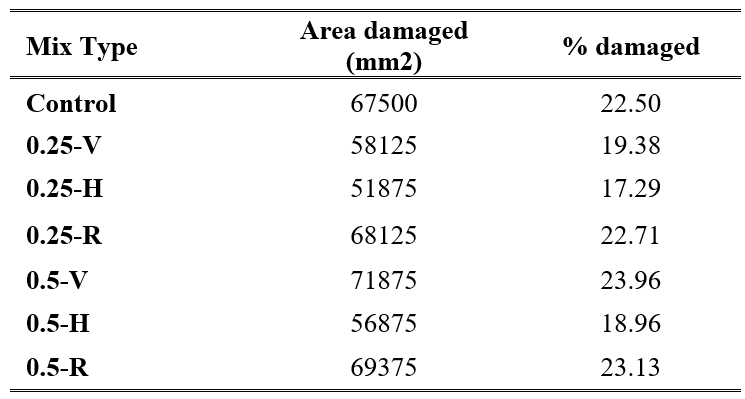
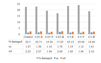
Figure 16. Summary of Ductility Ratios and Damaged Area for All Beams.
This study employed a combination of experimental and numerical methodologies to assess the structural performance of SFRC beams under varying fiber dosages (0.25% and 0.5%) and orientations (horizontal, vertical, and random). The following conclusions are of particular significance:
Future research should concentrate on the development and validation of experimental methods to achieve controlled fiber orientation within RC beams, thereby addressing the challenges encountered in the present study. The investigation of innovative techniques, including magnetic alignment, mechanical placement systems, and tailored casting procedures, to position fibers at specific angles has the potential to significantly advance the practical application of oriented steel fiber reinforcement. Furthermore, the implementation of advanced finite element methods (FEM) approaches, encompassing meso-scale and discrete fiber simulations, is imperative to achieve a more precise depiction of the effects of fiber orientation on concrete behavior. These advancements are poised to enhance the predictive capabilities of numerical models and support the optimization of structural performance in fiber-reinforced concrete applications.
Cite: Dayaa, L., Assaad, J., & Khatib, J. (2024). Effect of Volume Fraction and Orientation of Steel Fiber on The Structural Performance of Normal Strength Reinforced Concrete Beams. Steps For Civil, Constructions and Environmental Engineering, 2(4), 34–50. https://doi.org/10.61706/sccee12011135
![]() Copyright: © 2024 by the authors. Licensee Scientific Steps International Publishing Services, Dubai, UAE.
Copyright: © 2024 by the authors. Licensee Scientific Steps International Publishing Services, Dubai, UAE.
This article is an open access article distributed under the terms and conditions of the Creative Commons Attribution (CC BY) license (https://creativecommons.org/licenses/by/4.0/).


An independent academic publisher with an editorial team including many of the top researchers in the world. SSG publishes research, review, and case report articles in double-blind, peer-reviewed, open access scientific and academic journals.
Copyright © 2025 Scientific Steps International Publishing Services LLC (Dubai – United Arab Emirates)